 Alternator that looks like a Generator
Having a one-wire Delco alternator on the Jeep has always bothered me, it looks out of place and is a dead give-away that the Jeep has something post-war on it. So, I looked into a Powermaster Alternator that looks like a generator… and after several modifications, I got it to work! Here’s the entire process from start to finish!

As I still attempt to diagnose the strange sound coming from the rear of the Jeep, I started a new project this week. The Jeep is pretty much done (other than the sound), and it’s only cosmetic changes I’m working on. So let’s dive in…
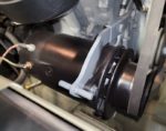
Since I bought the Jeep, I’ve had a post-war one-wire alternator on the Jeep. Shown here when I was rebuilding the engine in 2019. Wartime Jeeps had generators, not alternators on the engines. It’s pretty common to find alternators on Jeeps these days since many are 12 volts. 12 volt generators are massive and it’s a lot easier (and more reliable for charging) to use an alternator. Let’s take a look at how this all started…

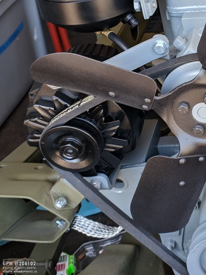
Here’s a look how the one-wire Delco looked when I first got the Jeep and when I took it off. It’s great it’s a one-wire alternator, meaning only wire is necessary to have it function compared to other alternators that need more wires to stimulate (‘wake up’) the alternator. The alternator pivot arm, shown on the bottom left of the second photo, appears to be a mix of custom-made parts and a post-war alternator mount kit.

To make it blend in better, I masked off any areas that go into the alternator and painted it a satin black.
This made it look better than before, but it still looked like a post-war altenrator. At least it wasn’t an instant eye-sore compared to the rest of the engine.
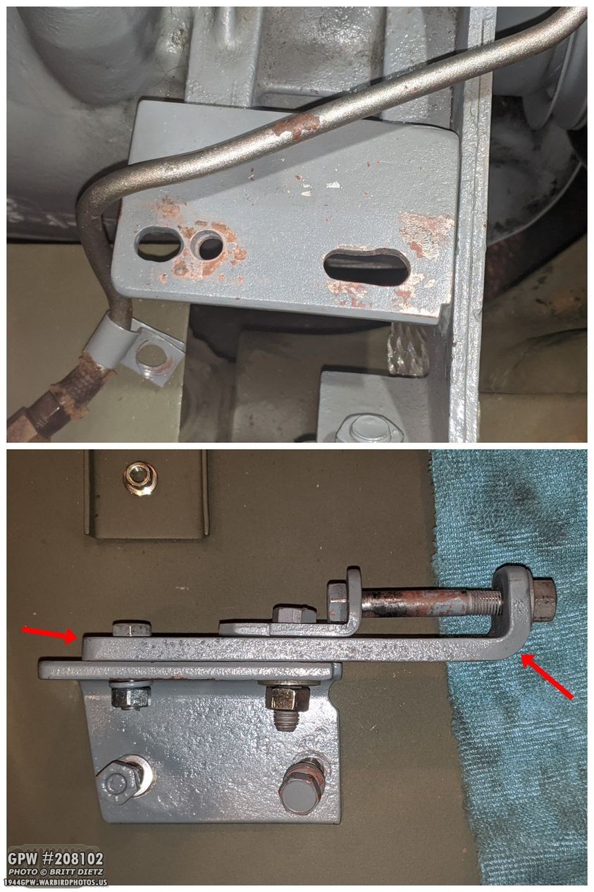
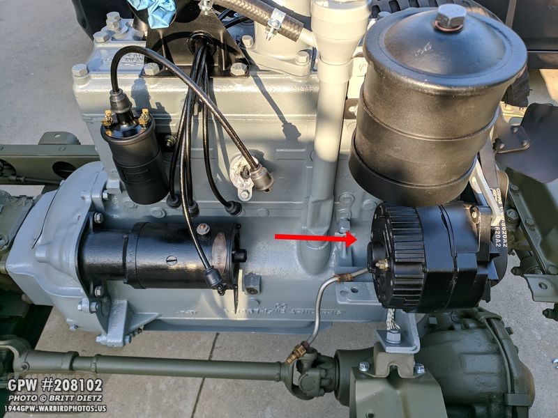
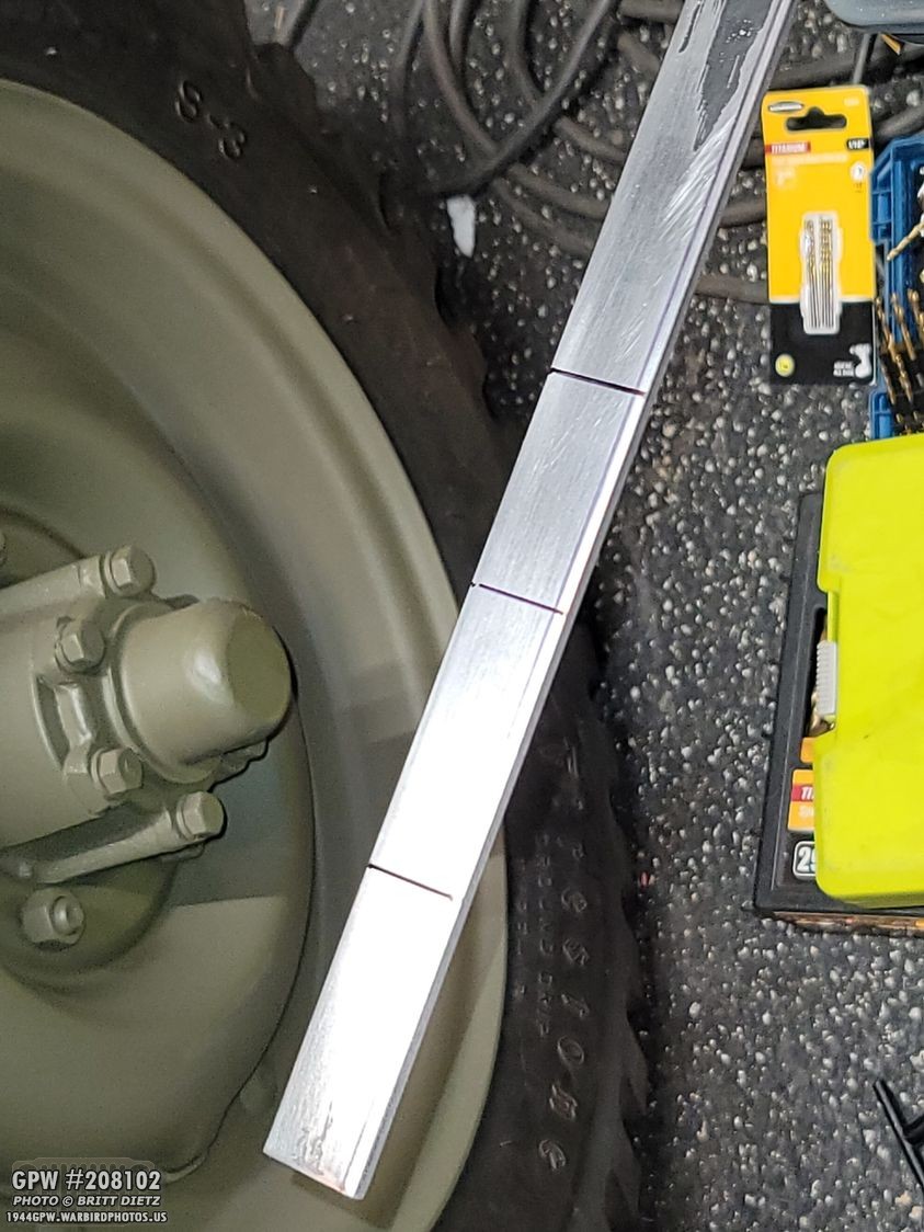
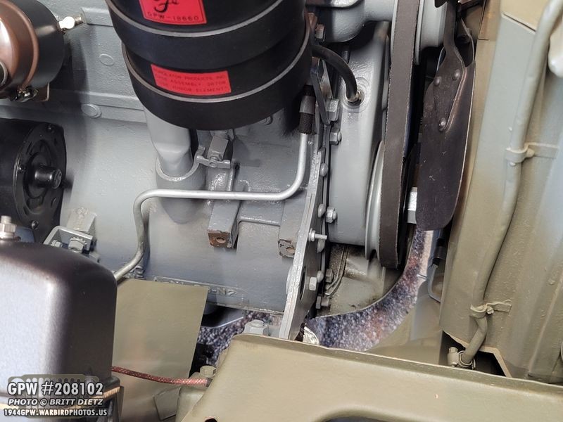
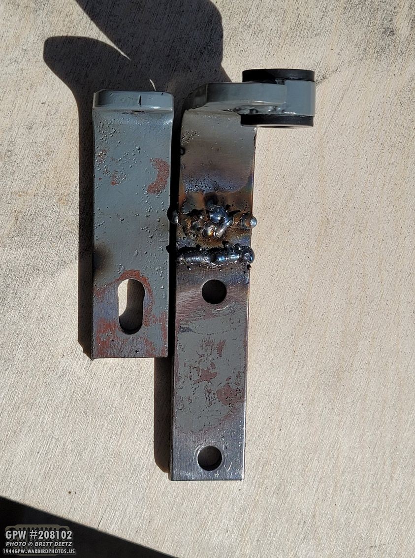
The engine block mount was also custom-made using a variety of parts. It took a bit of work to figure out how it all came together to hold the alternator. There was a large right angle base plate, a long skinny plate, and another small right angle bracket with several bolts. If you’ve been following the updates, you’ll know that the long bracket (red arrows) is something special…

That long bracket happened to be the remains of a heavily modified original GPW generator bracket. I’m pretty confident it’s the original one to my Jeep, that was taken to the grinder and welder to modify to fit the alternator. Sad day! You can see, one of the holes was elongated, the end of the bracket was shortened which you can see the half of the other original hole, and a new hole was drilled. The top of the bracket was ground down and the large circle flange that holds the rubber bushing was removed. A new hole was then drilled. Heavily modified!

When I put the Jeep back together, I just used that same ‘bubba’ mount plate and the alternator mounting arm.
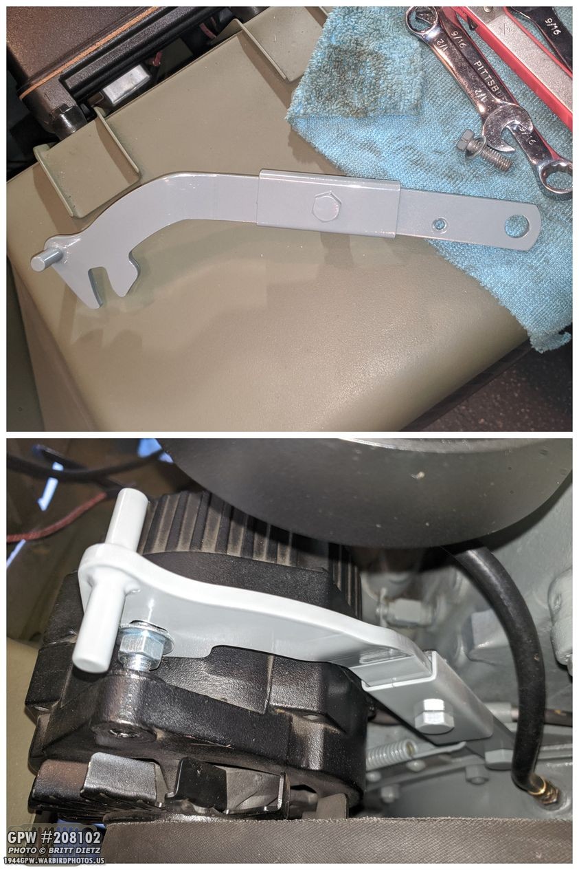
Last year, I splurged and got a correct GPW pivot mounting arm, and was able to install that with the alternator with a little work. A step forward to making things look a little more correct.
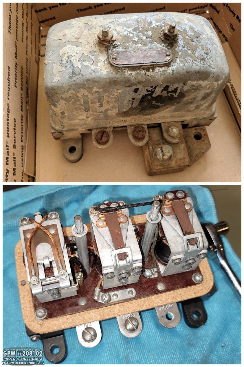
In 2019, I picked up an original 6-volt voltage regulator off e-bay. While the outside looked pretty bad, the inside was immaculate and probably works just fine. I put a new cork seal on it and went to work restoring it. I couldn’t use it, since my Jeep is 12 volts, but it needs to at least be there to complete the engine bay.
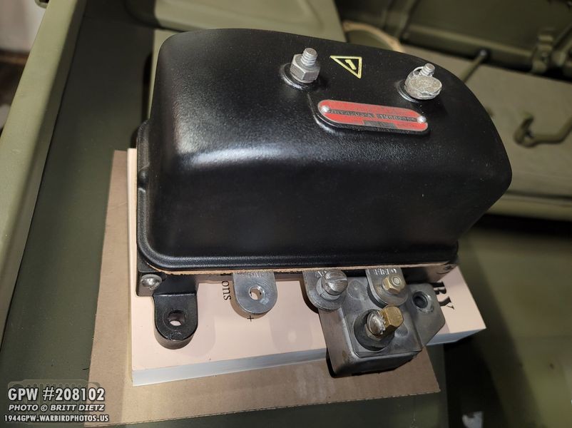
After a few weeks of restoration, researching the inspector’s stamp and perfectly mimicking one… here’s how the finished voltage regulator came out.
To give the ‘appearance’ that the regulator was hooked up, I hooked the power cables into the first BAT terminal, which would basically act as a bypass. This gave the appearance of it having something hooked up. And this is how the Jeep has been for almost two years now. But I wanted something better… something more correct without having to spend a ton of money switching back to 6 volts.

Here’s a look at a L134 engine from the 1945 ORD9 parts manual for Jeeps. You can see the generator that would be mounted on the side of the Jeep. There are three terminals, the top terminal would have the red wire coming from the ARM terminal on the regulator, and the green wire would come from the filtered FIELD terminal. Late/Post-war 12 volt generators are HUGE. They barely fit in Jeeps, so that was out for me. There are other 12 volt generators out there, but that would require me to replace the insides of the 6 volt regulator I had or, buy another one all together.
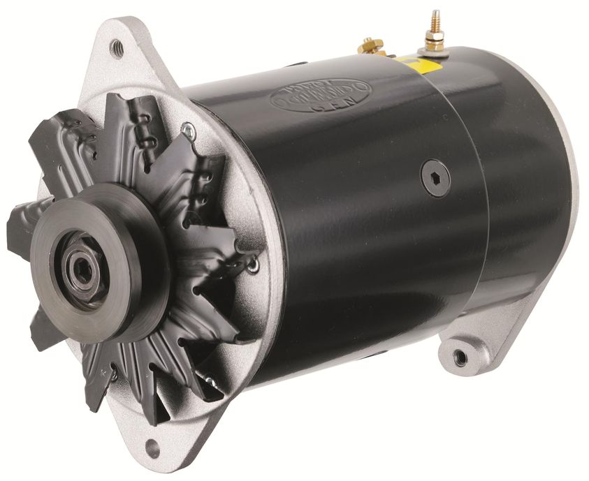
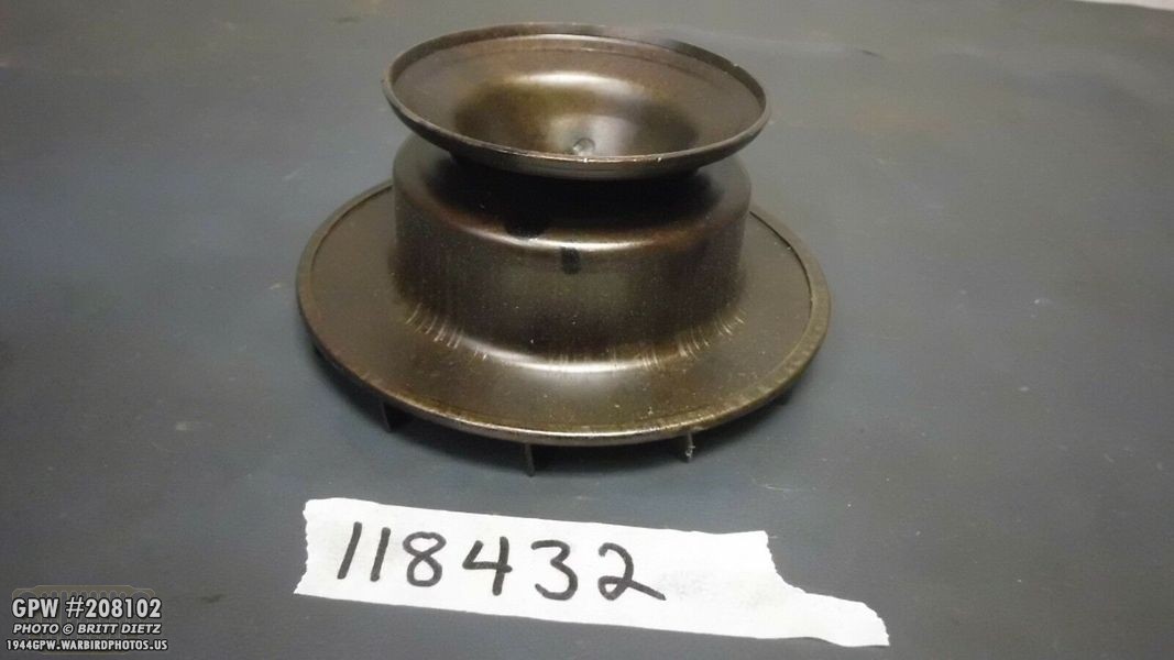
That’s when I discovered this. A company called Powermaster has a line of ‘PowerGen’ Alternators that look like generators. This company appears to be the only ones who do something like this and mass-produce new alternators.
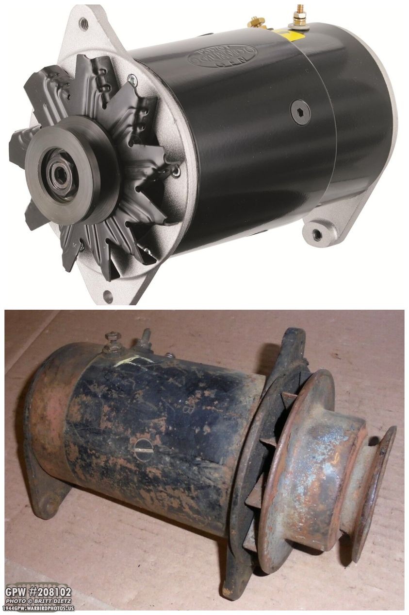
Comparing the PowerGen alternator with an original generator, they are close in design. There are differences, of course (wrong pulley, it’s not the same circumference towards the rear, not all black). But it’s a million miles closer than the one wire Delco I had. The PowerGen appears to be modeled after a Delco style generator.

Looking over the fact sheet for the alternators, this is the only style they have that’s close, and they offer a ‘short’ and ‘long’ case version. The long case version is about the right size for a WW2 Generator, with a ear gap of 7.13 inches vs 7.25 on a WW2 generator. That’s close enough! Also, I noticed they have a -2 model (82051-2) that has a second terminal for a dash light!
It was then I had a light bulb of my own… I think I could make this PowerGen 82051-2 alternator, and my voltage regulator, look like they are properly hooked up! I started to look into my idea… I would need to build a custom bypass plate in the voltage regulator. Since the red wire on the original generators is on top, and the top terminal is for the lamp, I’d have to make it so the BAT terminal and the FIELD terminal connect, but the ARM terminal (center) ends at the terminal. I’ll explain this better later.

Now, these internals are so immaculate, I don’t want to destroy them by doing this. So I decided I would need to build a custom plate with custom terminals to make this work.
Taking out the original internals, here’s what I started with. Just the base and the cork gasket.

I measured and cut a base plate out of non-conductive hardboard (same thing pegboard is made out of, minus the peg holes). One side is coated, the other side is brown.

After drilling the four mounting holes and larger holes for the top cover posts, I rounded the corners and checked the outer cord gasket seal… perfect fit!
I then went out to home depot, and found 1/4 inch strips of metal to make the terminals. This is way too thick compared to the original terminals, so I would have to grind down the thickness 11/64. Here I’ve marked out the three terminals.

It’s a LOT of work to grind down that much metal and give it a nice uniform half circle end, but here’s the first test terminal. I then drilled a hole at the end, and tapped the correct thread size for the large terminal machine screws. I then used a small #10 screw with a nut to hold the terminal to the hardboard plate. The terminal screw fit on perfectly, and the cover went on just like normal! Perfect!

Here are the three final terminal posts before I went to work drilling the screw holes. This took several hours to get all those darn things thinned down, rounded, and ready for drilling. The cork gasket underneath each of the terminal posts prevent grounding, and the deeper area in the base allows for the screws holding the terminals to the base not to contact anything inside. Perfect.
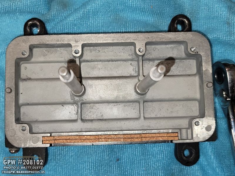
After drilling the holes, here’s a look inside how it’s bolted. I made a custom loom wire (in the WW2 wiring harness style) that basically bridges the connection between the FIELD and BAT terminal posts, but the middle ARM terminal post is not connected to anything and ends there. The FIELD terminal, on the right, is going through a WW2 radio filter. This is just a pass-through frequency filter, so it won’t affect the alternator’s output power.
Putting the cover back on, here’s a final test to make sure everything looks good. So far, so good!

I then mounted it in the Jeep to check how it’ll look… looks legit to me! The first wire comes from the ammeter.
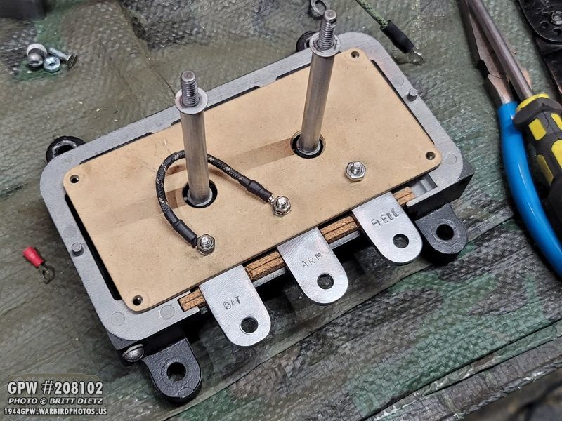
I then went and bought a punch set about the same size as the punched letters on the original terminals. They are not easy to use, but I got them close enough with the BAT, ARM, and FIELD punches. Ignore the fact that the loom wire is going from BAT to ARM, this was a temporary test I was doing with the Delco one-wire I had on the Jeep.

I did take some time to refinish the wrinkle paint on the regulator cover. After sanding it down, I used all of the paints you see above to get that finish. I used the VHT wrinkle plus, which never seems to come out how I’d like, even after extreme heat… this time I added some matte hammered black over the VHT wrinkle paint. That gave it further texture, but also made it look a bit more gray. So I painted it with a flat Rustoleum black paint, and then topped it off with a matte clear. This is the result.

Putting it all back together with a lead seal, here’s how it looks. You can barely see the punched lettering, but at least they are there.

As things started to come together, another item I got in prep for this is a correct MB generator bracket. This is an original bracket, so I was told. No F stamp, but you wouldn’t see it if there was one once it’s mounted, so I didn’t care much. I got a hardware/rubber bushing kit from Ron Fitzpatrick Jeep Parts and inserted the rubber bushing. Some of you may remember me doing all this last year in November as I knew, one day, I would either get a generator or something.
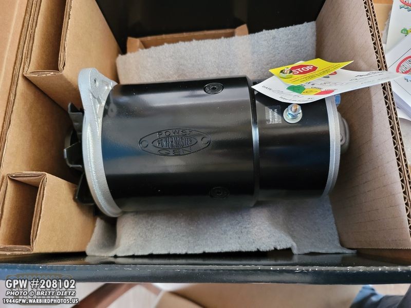
I then went and pulled the trigger, I got a Powermaster PowerGen 82051-2 alternator! It arrived after a few days. It was about $350.
I wanted to check if it would even fit, as if it wasn’t going to fit at all, I would try and return it. So I removed the Delco alternator, the bubba mount setup, and the post-war alternator pivot arm.
Before I could do that, I need to add the rubber bushing to the front engine plate. This was a PAIN to get in there. That rubber did not want to compress to push in. After using a screwdriver to carefully push it through, it finally ‘snapped’ into the correct spot.
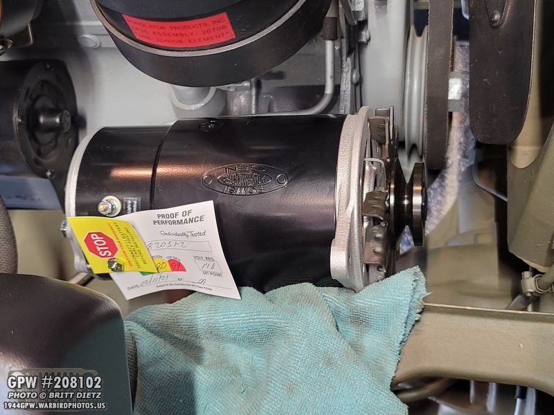
I then put in that original generator engine bracket that I had ready since November, and carefully put the PowerGen into place… and right away, three MAJOR issues were very apparent.
Side note – See the proof of performance tag? It was tested February of this year, just last month! This is a heck of a brand new item!

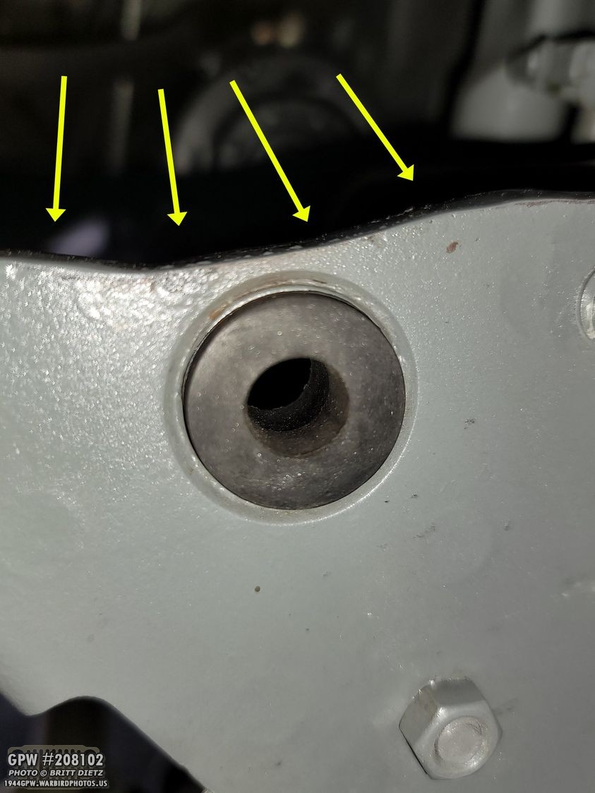
PROBLEM #1: The PowerGen is too fat/the front ear is not long enough. As you can see, the front bolt does not line up with the hole.
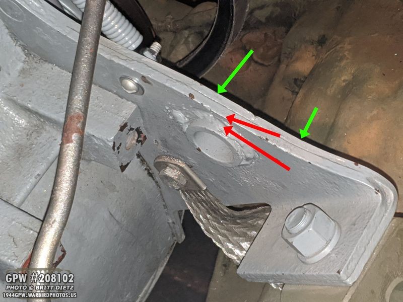
What does that mean? The thickness of the plate (red arrows) will need to be shaved down between the two green arrows.
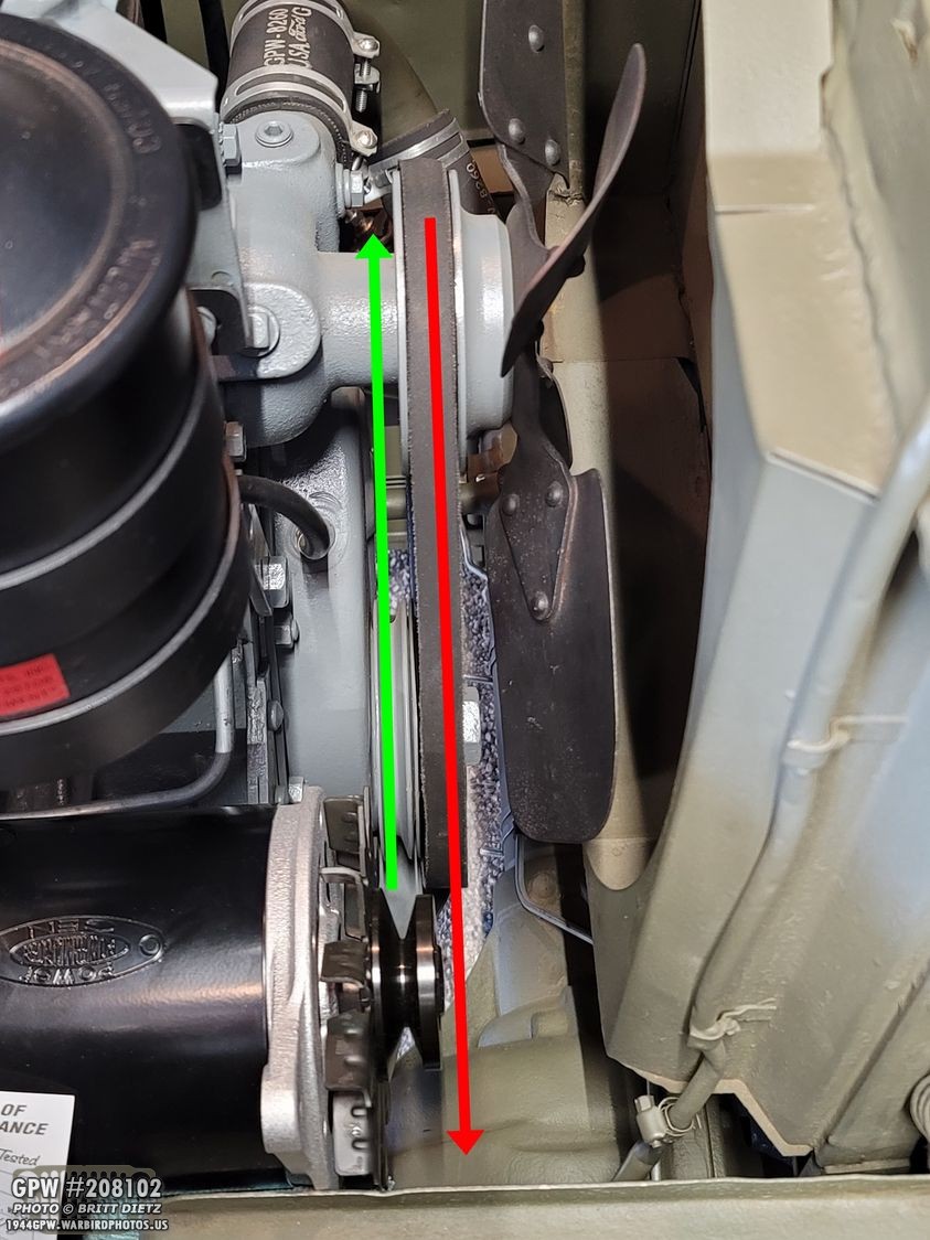
PROBLEM #2: The pulleys don’t line up. The short pulley that came with the PowerGen (green arrow) is not tall enough to line up with the water pump pulley (green pulley). What does that mean? I need a taller pulley. And I was told that a WW2 generator pulley might work…

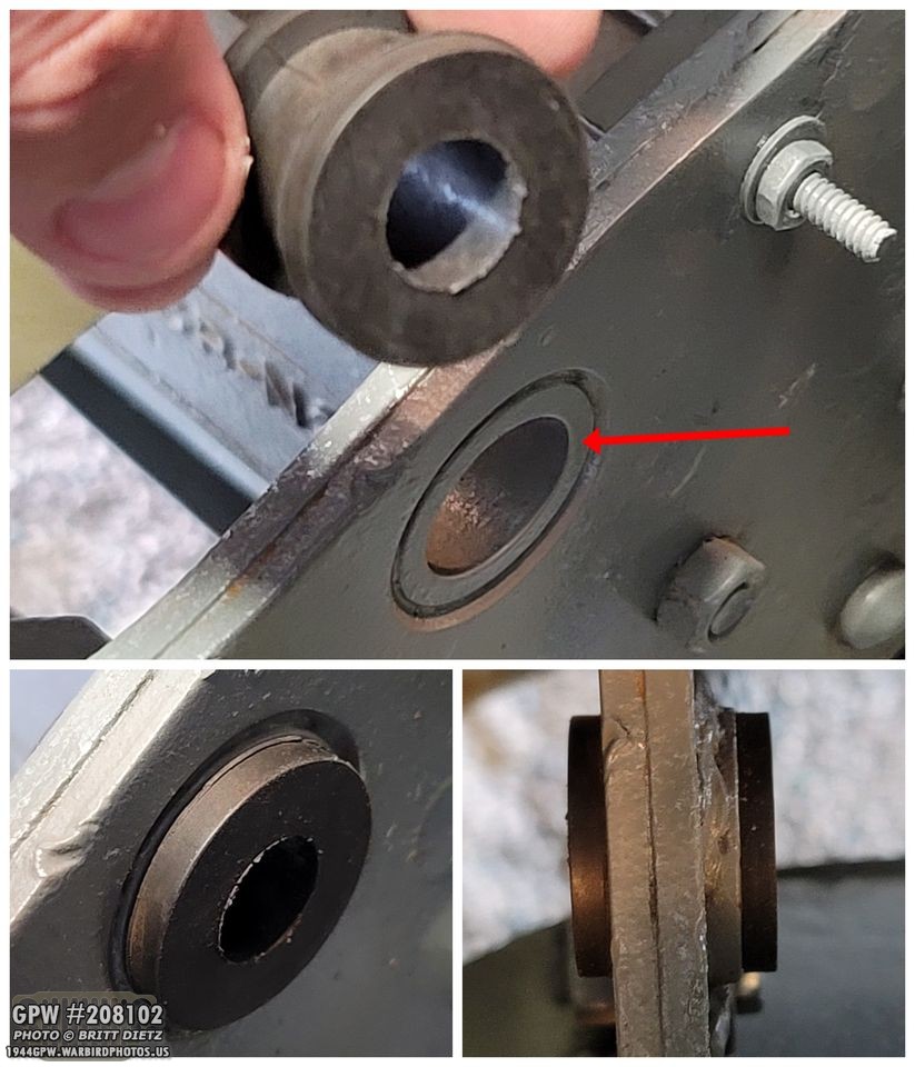
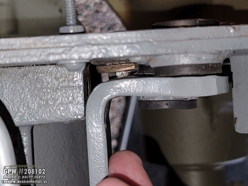
PROBLEM #3: For some reason, the generator bracket I had gotten wasn’t quite right. If you look here, you can see that the generator bracket rubber pushing doesn’t line up with the same bushing on the front engine plate. Hmmm. Here’s a punch going between them, showing quite a huge angle.

The two ears on this PowerGen are aligned, just like a real generator. So that means this generator bracket is not right.

So, what does that mean? I’ll need to extend the circular flange and rubber bushing so it is out further to match the front plate. At the time, I didn’t realize it but I’d also have to extend the length of it as well. More on that later.
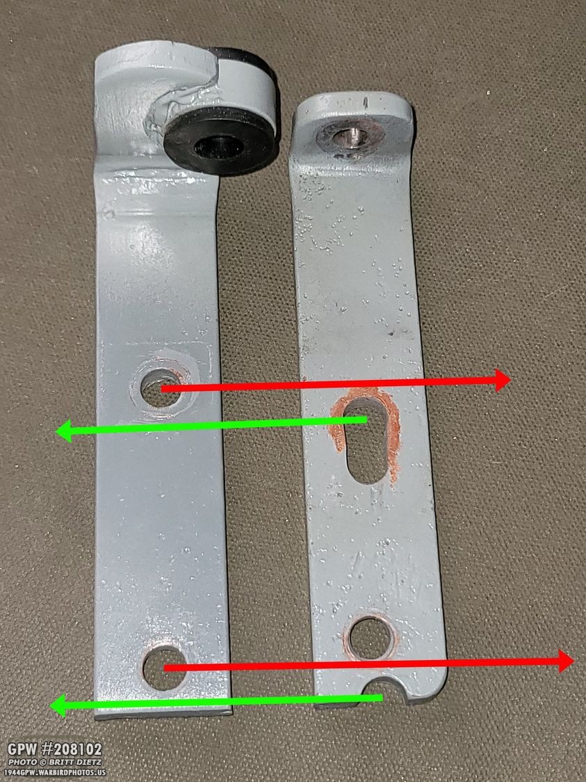
Taking that remnant of the original GPW bracket and putting it next to the (I was told) original MB take-off bracket, here’s how different they are. When lining up the part of the brackets where the rubber bushing would be, notice that the holes don’t line up.

If I line up the holes, there’s a big difference in how much more extended the GPW remnant bracket is. Hmmm! This will be key later.

So, thinking I only needed to raise the circular flange and rubber bushing up about a half inch, I decided I’d use a section from the GPW remnant since it’s the same thickness, and weld it on to extend the new bracket.
Holding that bracket up to the front plate, you can see just how far off they are from eachother. The rubber bushings should line up.

So I cut the end off the bracket right after it curves up. I then cut a small section from the original bracket to raise it up.

Welding them together and smoothing out the welds, perfect! Now they are aligned!

After priming and painting Ford Engine gray, it’s ready to go (or so I thought).

That’s when I noticed another issue with the bracket. See how much space is between the end of the bracket and the front ear? That would mean I would need to add washers to the front bolt as it won’t be flush against the front rubber bushing on the engine plate. Hmmm.

But that presents another issue. I HAVE to keep the rear ear of the PowerGen right up against the rubber bushing, as I will be adding the correct bond strap going from the starter front mount bracket to the bolt that holes the PowerGen to the generator bracket… But, if I do that, then the front, which will be more forward, puts the front pulley in a spot that a WW2 pulley will be too tall, and the included pulley will still be too short. So, I need BOTH ears to be against the rubber.

This made me realize, I need to make this bracket the same as that GPW remnant. Even though I’d used a portion of it, I realized, I should just line up the hole and extend that area to where the bracket curves upward. Here’s my solution… I cut another section of the remnant bracket (left) and will extend the take-off bracket (cutting it again). Looking back now, I realize that I got some weird generator bracket. I think if I’d just gotten a F stamped NOS bracket, it would have fit and I wouldn’t have had to do these two extensions.
While welding I was careful to keep checking the alignment to make sure they matched the engine way.

Smoothed and painted, a perfect fit. I couldn’t have made it more perfectly sized if I tried! Being that I’m still a beginning welder and metal-fabricator, this was a big accomplishment.

Now, to solve the problem with the pulley not lining up, as mentioned, I started looking for a NOS pulley. Taking off the pulley on the PowerGen here’s what we have. A tall spacer (red arrow) spaces the pulley away from the front face so the fan blades don’t hit. The threads and the shaft are not that long, and I was a bit worried that a WW2 generator pulley wouldn’t fit.
I picked up this WW2 pulley on ebay, which came a few days later.

Here you can see the drastic difference between the included pulley, and the WW2 generator pulley.

Putting the pulley on, I found that with that long spacer (not shown, go back two photos), the pulley was too far up on the shaft and I couldn’t get the nut to go on. So, I would need to get washers or another steel spacer that I could shave down to ‘shim’ the WW2 generator pulley against the bearing and shaft of the PowerGen. It had to be a specific inner and outer diameter, however, as whatever I use needs to only contact the metal inner part of the bearing.

Sadly, I realized I didn’t take a photo of my solution, but I can explain it. I went to Ace Hardware and found ‘machine bushings’, which are basically specially sized washers. Here’s the only photo I got of one of them (one I didn’t use). I ended up using five total, which was the sweet spot. Four, and the fan blades hit the face. Six, and I couldn’t get the nut on. I also had to take the Dremel and slightly ground the inner diameter a little bit larger as they just barely didn’t go on the shaft originally.

With the five machine bushings on, as you can see I’m left with only a little bit of threads. It’s enough to get the nut on and spin it a few times, so it’s on about half way. I’ll use thread locker in addition to locking it down tightly.

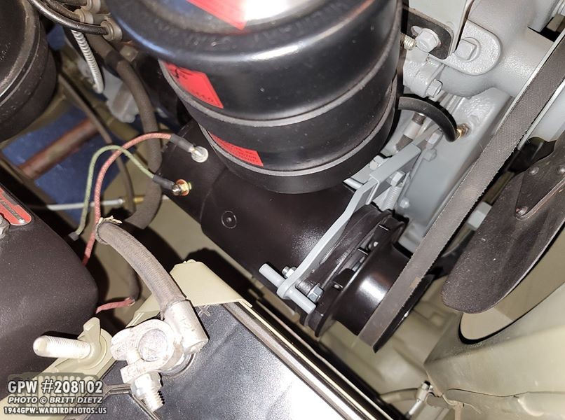
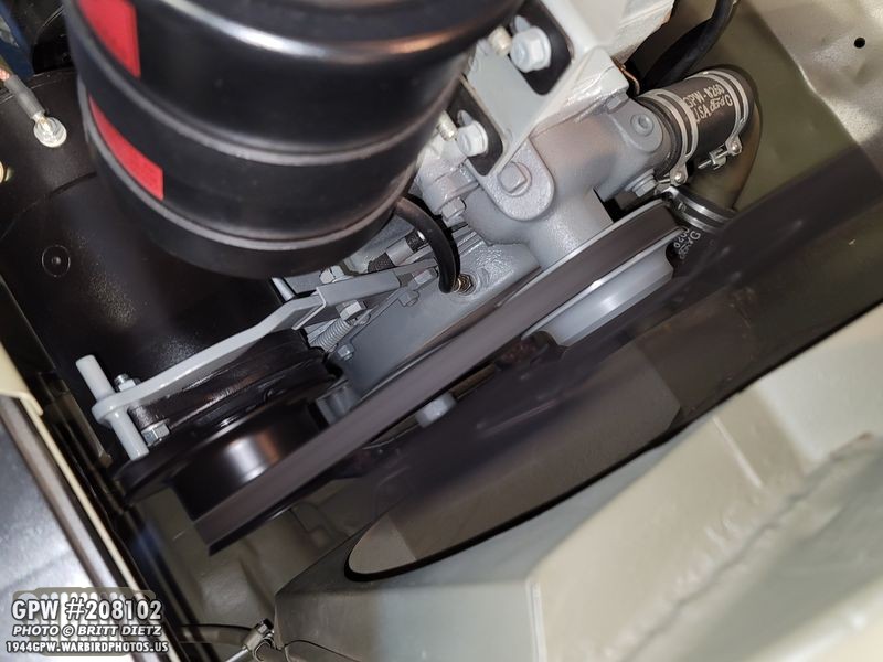
Putting the PowerGen back in with the WW2 pulley and the now correctly twice-extended generator bracket, SUCCESS! The belt lines up! The ears of the PowerGen also perfectly and snugly slide onto the ribber bushings! YAY! One more problem left to fix…
I took the angle grinder and carefully stripped down the engine plate and smoothed it out, as you can see here. This was plenty needed. I then repainted it Ford Gray.

And the real test… does it fit now that I’ve solved all three issues? YES! Perfect fit in all places! YES!! But, I still need to paint it all black. Before that, however, I wanted to see how the hooked up voltage regulator will look.

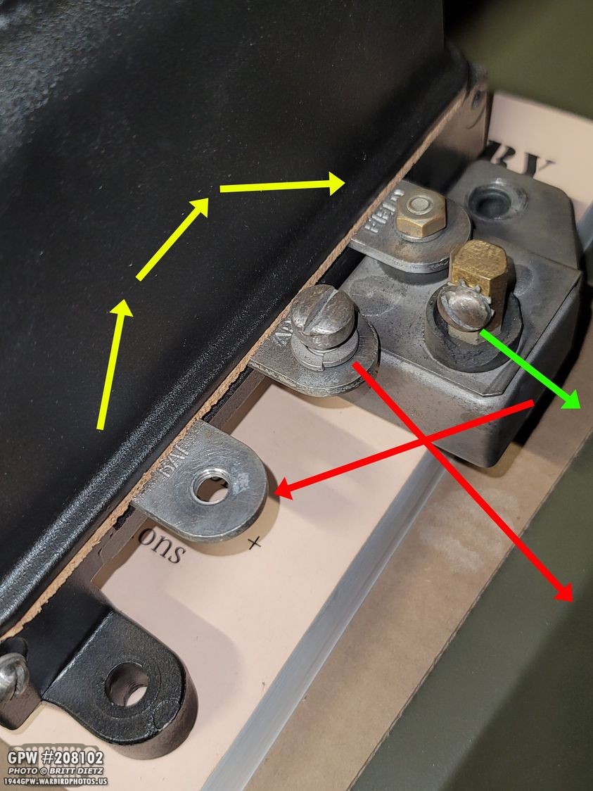
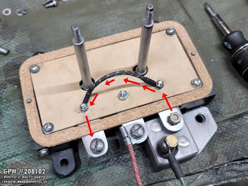
Here, I’ve overlayed over the regulator how the inside looks (in photoshop) so you can see exactly how this will work. So, the top terminal (yellow arrows, red wire) is the lamp light terminal. That goes to the ARM middle terminal, which is not connected to anything, so that is terminated without making any circuits. No power will flow through that. The bottom terminal is the power from the alternator. It goes through the green wire to the regulator filter, to the FIELD terminal, then internally with that loom wire to the BAT terminal, and then out with the red wire to the ammeter. This will mimic the correct setup for a regulator and generator!

A couple more views of the wiring test.

Now it’s time for painting! I first painted the generator pulley and the whole PowerGen (after very carefully masking off any areas that go inside) after some scotch pad sanding with the flat matte black. I also used some bondo to fill the engraved PowerMaster logo on the PowerGen, and also the engraved BATTERY marking next to the lower terminal.
After that dried, the magic happens when I spray the clear coat satin. This gives it a perfect finish. Starting to really look like a generator now huh?
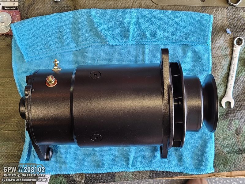
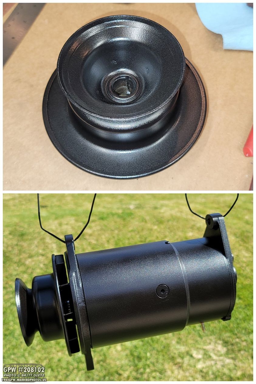
TADA!! The finished product! That is one heck of a generator-looking alternator!
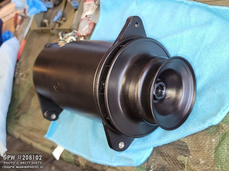
Here’s a look from the front showing the WW2 pulley. That really takes it above and beyond.
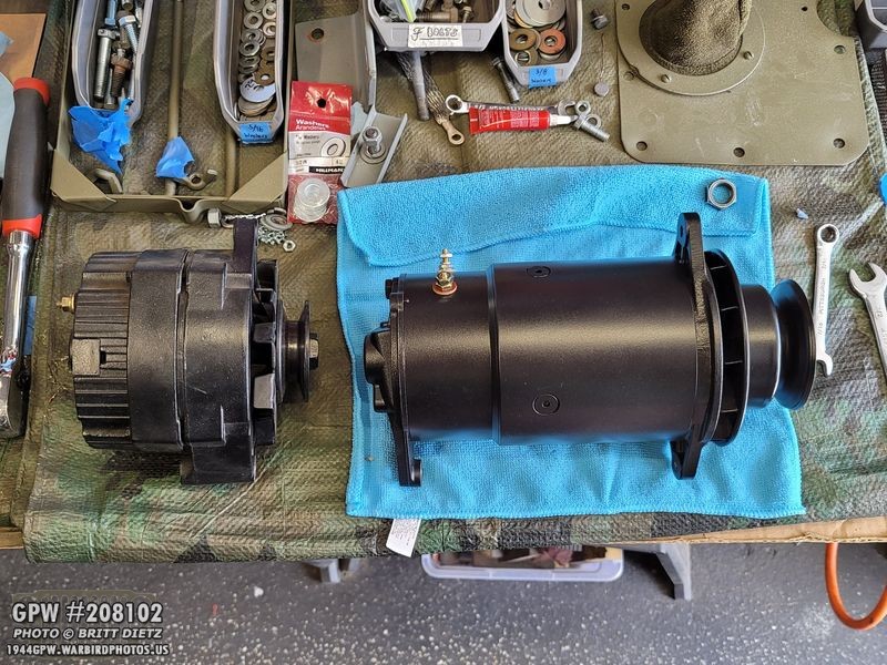
Let’s compare between the one-wire Delco that was on my Jeep before and the finished PowerGen. Night and day difference.

And here we go, finally installed! All is tightened down, voltage regulator wired up, and the PowerGen pivot adjusted so the fan belt has the proper 1/2 inch deflection!
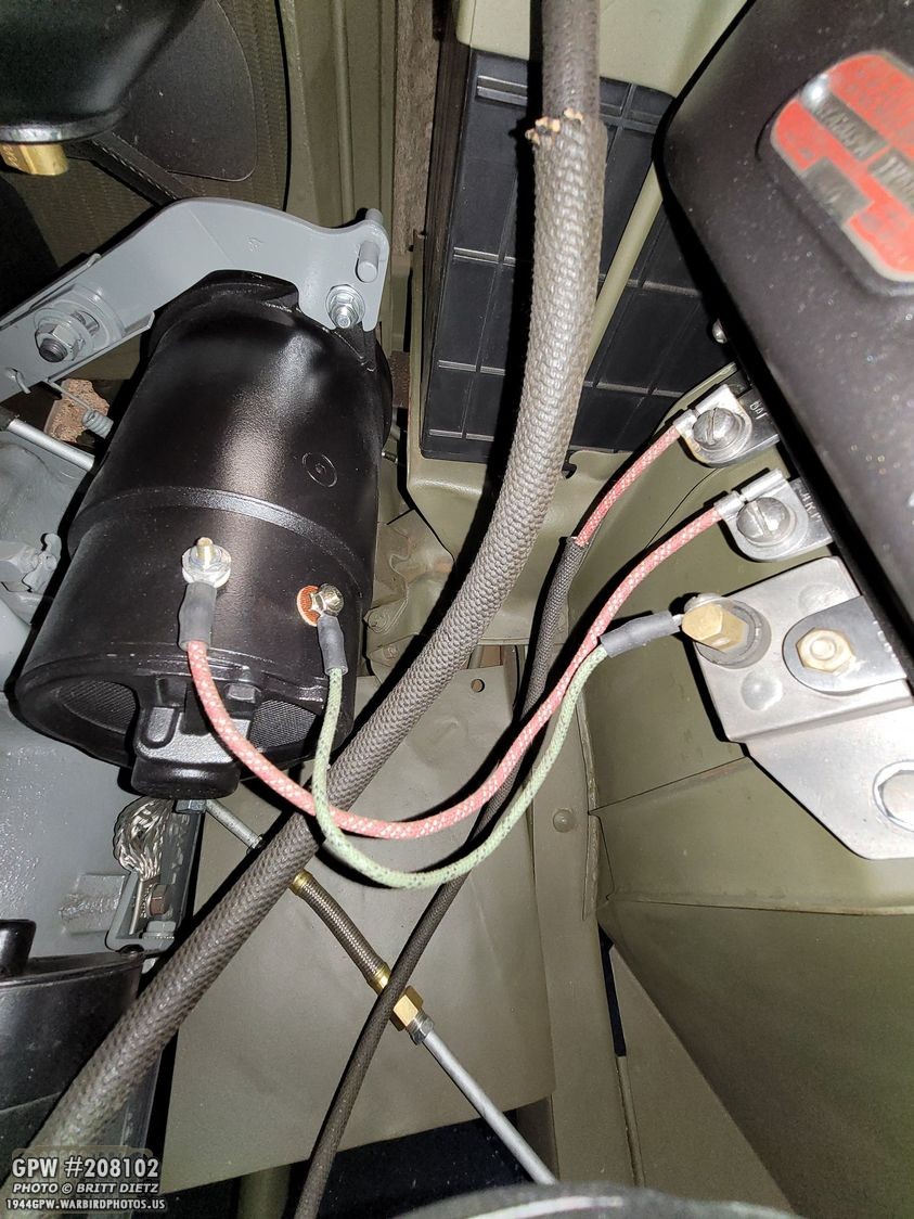
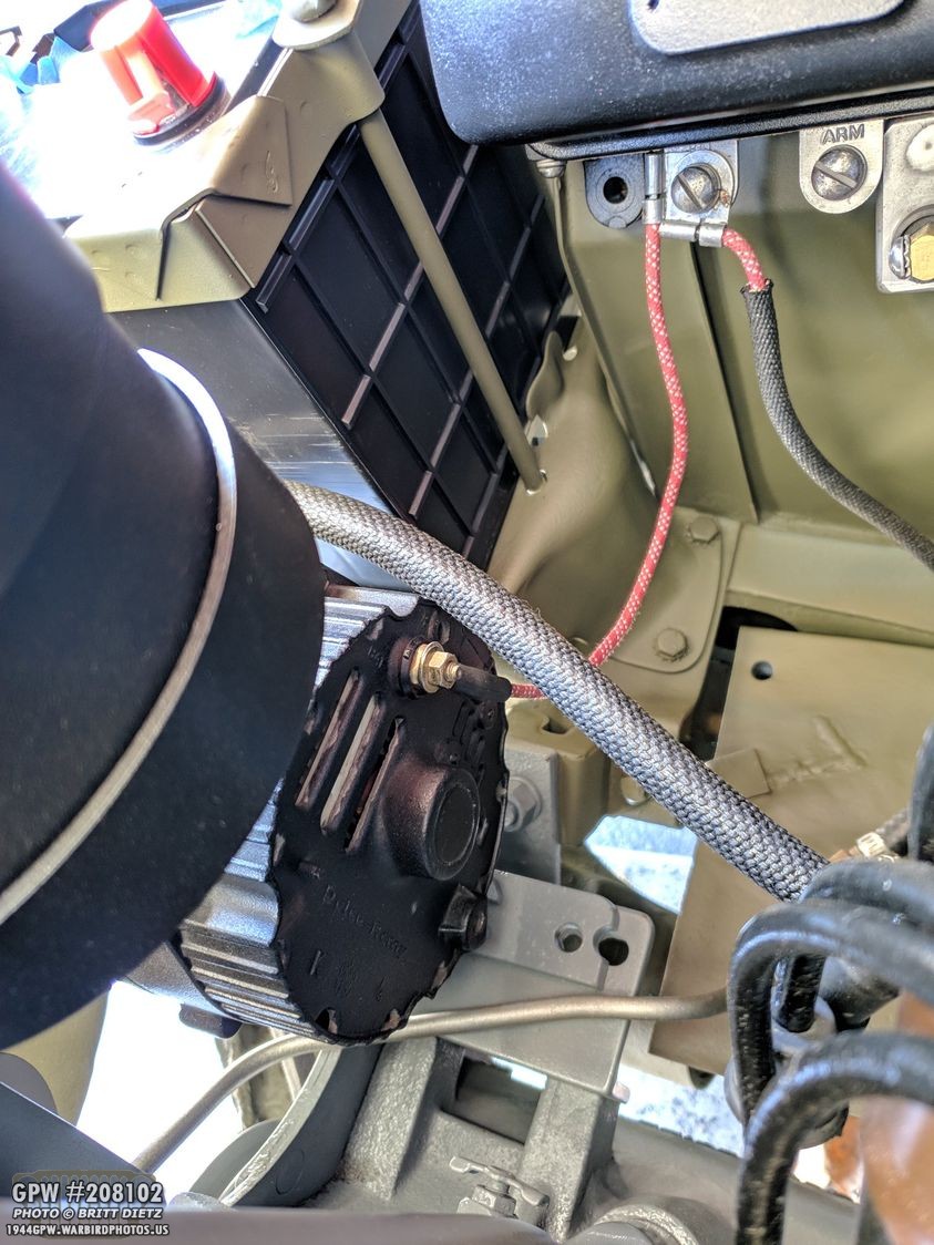
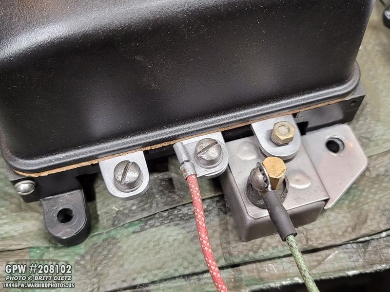
And here’s a look at the wires from the regulator. Looking so much better than before.
The arm is a bit further over and the PowerGen rotated a bit more towards the battery than I’d like, but I think the fan belt is a little stretched out due to the Delco alternator. I might eventually get another GPW fan belt to see if that will allow the PowerGen to rotate back a little more. It’s not bad, and there’s plenty of room between the PowerGen and the battery.

Another view of the voltage regulator hookups. Most people will not even realize this isn’t a correct generator on the Jeep!

The big question is now, does it all work? I knew it was a good unit, as there was that tag with the inspection tests last month, and I’ve tested continuity throughout the entire process also making sure the bond strap on the back ear of the PowerGen is giving a nice solid ground to the block and then to the battery.
So, I got into the Jeep and started it up! Right away, I noticed the Ammeter was well into the positive, more so than the Delco alternator! The belt spins perfectly, so the big question now is… what are the numbers?
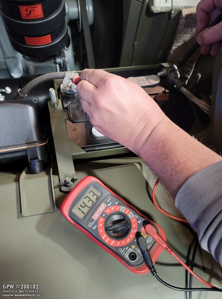
Using a multimeter, I tested the voltage while the Jeep was at idle… and it was a SOLID 14.33! That went up to almost 14.8 when revving the engine. That’s a perfect recharge, I’d say this whole operation was a giant success.

Knowing all is good with the voltage regulator custom internals, I went ahead and used my new wartime lead seal crimper to crush the seal. There’s been a lot of debate about what should be stamped on these. Many say it was AL for Autolite, but others say that’s just the inspector’s initials and other letters have been found. With many items, U.S. was stamped (like on ammo cans with lead seals), so I went ahead and used the wartime crimpers I got that have U.S. crushed. Eventually, I might get a different die to crush something else, but for now, this works perfect.

So, my thoughts overall… It was a fun (and somewhat frustrating) journey adding this. I LOVE the end results, and I think the photos speak for themselves. It’s another great feature for the Jeep to get it looking that much closer to the wartime style. If you’re thinking of doing this, provided you have a correct generator bracket and not a weird sized one like I had, then I think the biggest hurdle for you will be shaving the front engine plate down and shimming the PowerGen with a WW2 generator pulley. To set up the voltage regulator correctly, you’ll need to build your own internals or, if you using the originals, figure out how to properly bypass everything on all three terminals.

Taking the Jeep out for a few drives, everything appears to be working in tip-top shape with the alternator. I’m excited to have it in there and hope I’ve inspired others to be creative!

So, now we’ve come to the end. The next project to tackle is going back into the rear axle and try to figure out this darn clackity issue. Look for some other fun ‘extra’ projects in the next update. I’m not longer seeing the light at the end of the tunnel, I’m exiting the tunnel now with this restoration and just need to finish a few small things.
Till next week…