 D-18 Transfer Case Rebuild!
After last week’s rebuild of the T-84 Transmission, it’s time to turn the sights to the D-18 Transfer Case with a full rebuild, shimming, and shaft play checking. This one is a bit more complicated than the T-84 as there are a lot more steps that require various things to happen at once. Almost halfway done with the transmission/transfer case restoration/rebuild project!

After completing the rebuild of the T-84 transmission last week, it was time to set the sights onto the D-18 Transfer case! As you can see, I’m jumping ahead a bit as it’s already rebuilt for this photo. This week’s update won’t cover the external emergency brake rebuild nor the final sealing of covers, but mainly just the actual rebuild and shimming. Let’s get started!

Last we left off with the transfer case, it was painted with everything put together (no internals) to prime and paint OD Green. This is Ron Fitzpatrick Jeep Parts 33070 OD Green from an air gun.

Once the paint had dried, I removed all the painter’s tape masking and separated the output cover cap and the transfer case itself.
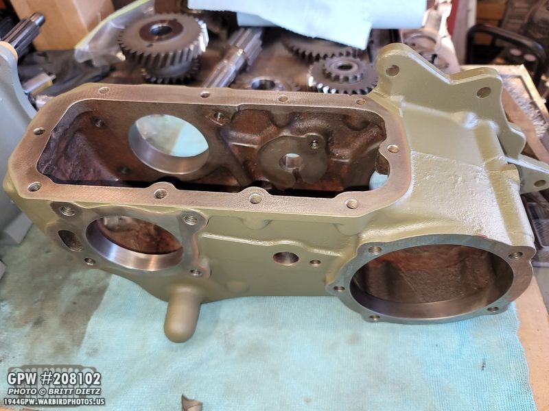
Let’s start with the transfer case. Turn it over and make sure the oil pan is removed. While I have a photo of this side, we’ll be starting on the other side first.
Take your long shift rod and insert it into the right hole.

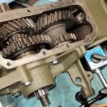
Here’s a look inside. This rod is what engages high and low gear with the shifter cane.
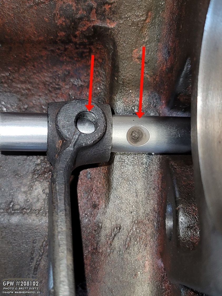
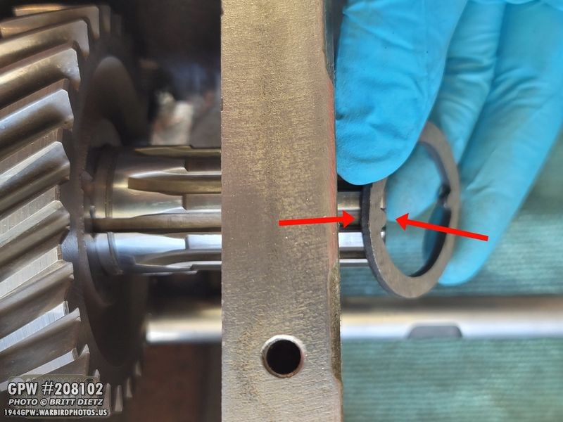
Before you push it into the hole on the other side, you need to attach the fork. The hole for the fork (left arrow) needs to line up with the hole on the rod (right arrow).
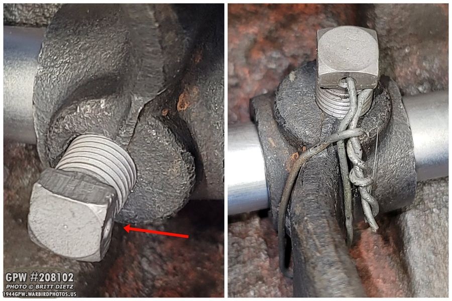
Once aligned, you can insert the shift screw. This screw has a block head with a hole for a safety wire. Once the screw is in place and tight, attach safety wire (I use 16 gauge wire) and make sure it’s tight. Mine isn’t super tight in the photo, so I went back and made it tighter. You also want to make sure it really hugs the shift fork, as if it sticks out too much it can impede the gear we’re about to install.

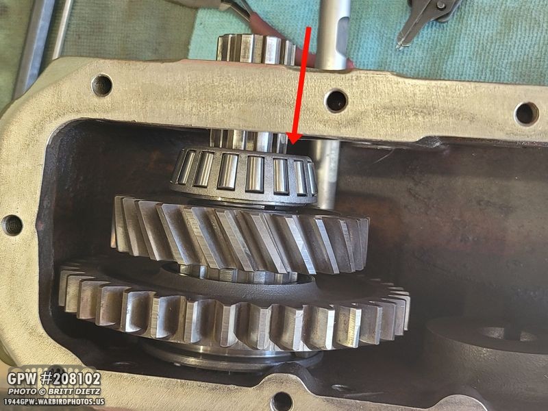
With the shift fork in place, screwed down, and safety wired, you can set the sliding gear into the fork. You can see the ends of the fork in the large slot groove. This is the high/neutral/low gear.
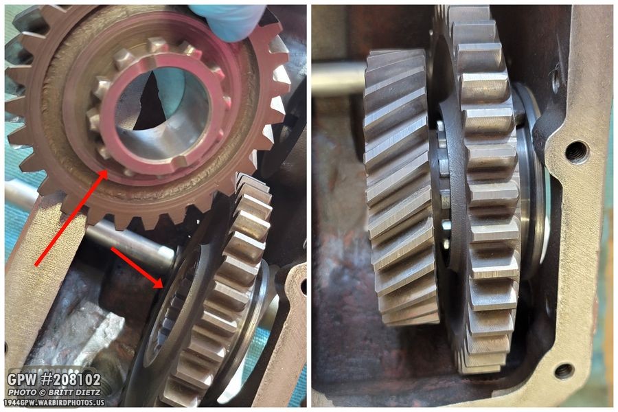
Next, you can put the output gear on. The smaller ring of teeth will actually fit inside the travelling gear as shown.

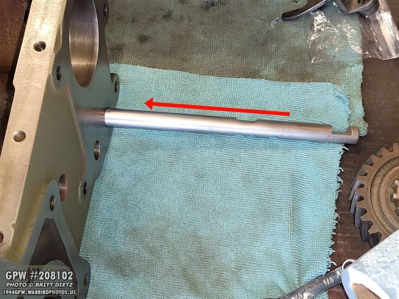
It’s time to install the output shaft! I’d had it soaking in a tub of gasoline for a few days to clean it up. After soaking, I cleaned it up with rubbing alcohol and then used a scotch pad to clean up any caked on grime.

Another fun shipment from Ron Fitzpatrick Jeep Parts with some new items for the transfer case including a second output bearing (I forgot to order two), shims, new clutch shaft bearing snap ring, main ouput shaft bushing, and a T-84 shift rod, which we already installed last week.

It wasn’t too hard getting the new bushing into the output shaft. Just tap it in until it’s flush with the end. But, you need to tap it in further, in fact about 1/2 to 9/16 inch deep.
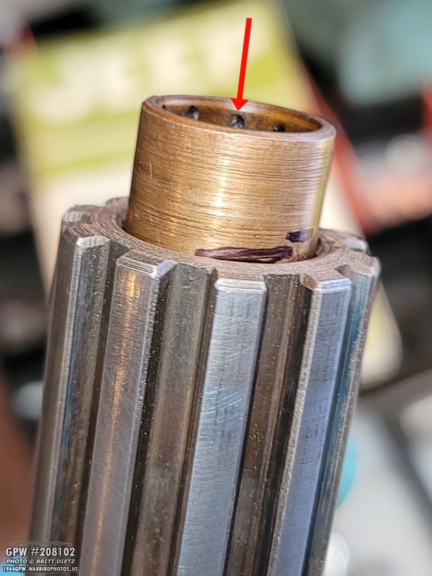
What I did was take the old bushing, take it to my belt sander and sand the outside of it until it wouldn’t get stuck in the shaft, marked 1/2 inch on the old bushing and used that to hammer in the new bushing. Once the line I marked lined up, it was deep enough! I could then take out the old bushing.

Now time to add the first output bearing on the output shaft…
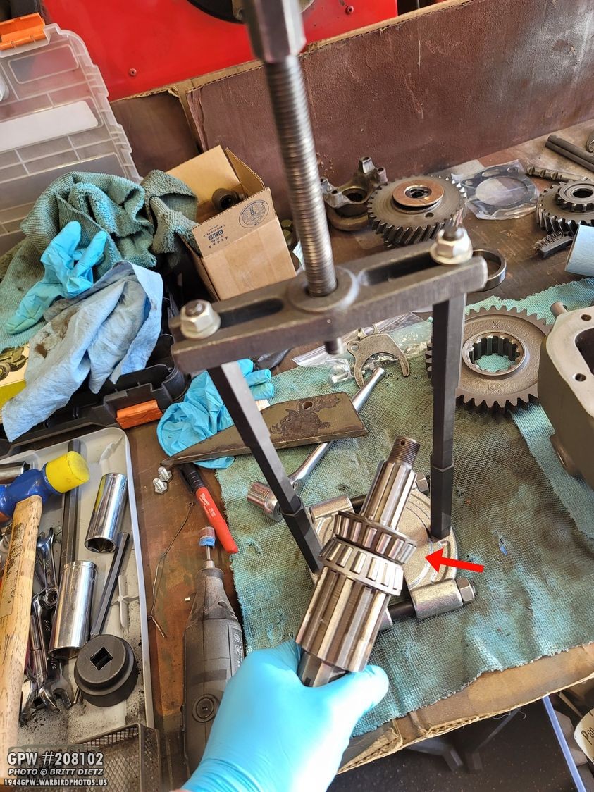
For this, I used my bearing puller (with extensions) to actually pull the bearing on. I took one of the old bearings, dremeled out the center so it was loose on the shaft, and actually used that with the puller to push the bearing on. Worked perfect.
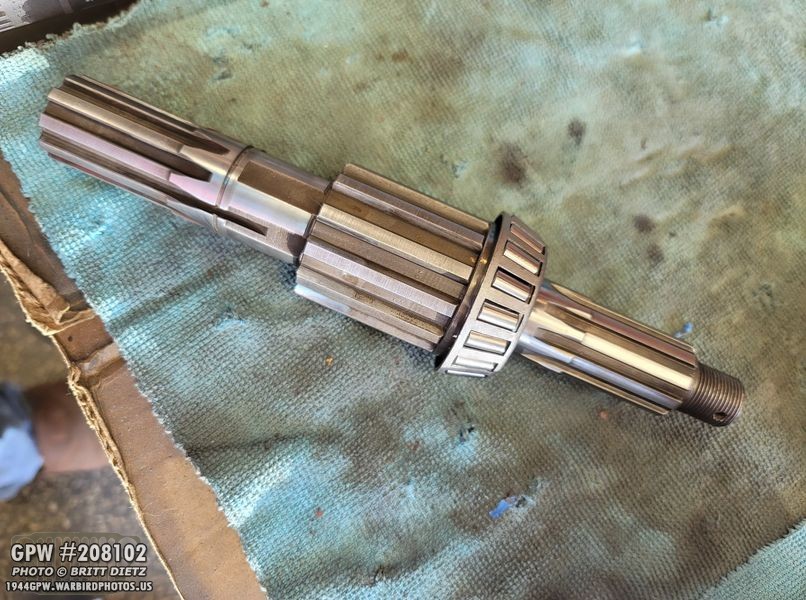
The shaft is ready to go! This is the original GPW shaft. New bearing, of course.

Now enter the shaft as shown, making sure to line up the teeth with the gears.

Now, take your special locking ring with the two teeth…
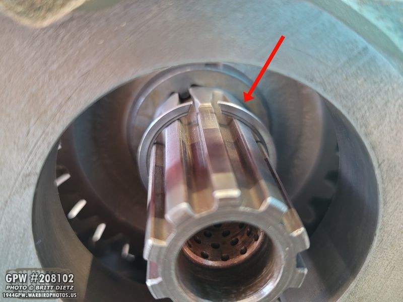
Go to the other side of the transfer case and insert that onto the shaft you just put in making sure the long teeth go where the shaft is deep and extends past the rest as shown.
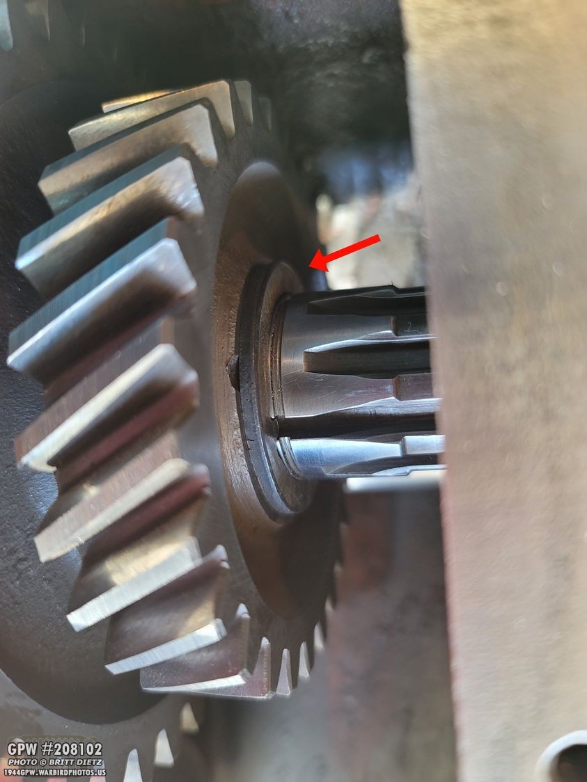
You should be able to push it all the way till it hits the gear.
To then lock that ring on, you need to add a snap ring. This is pretty simple to add. Just get it on the shaft, and carefully move it down.

The snap ring will find the slot and just fall in there. Now it’s all locked in place!
Time to add the other bearing! I slightly heated the bearing so it would go on the shaft easier. But it didn’t seat all the way, so I’d need to tap it on more.

For that, I used that same bearing that I dremeled the inside and used it to tap the new bearing all the way. I used a bunch on the backside of the old bearing to tap it in.
Now that the bearing is in, on that same side, tap in the bearing race. Make SURE you place it in the correct way (used the bearing you just tapped in to verify). I used the old race to tap it in. Get it to about flush with the metal. You don’t need to make it perfect, but don’t tap it in further. The next few steps will set the correct depth for that race.

To set the depth of that race, you need to install the output cover/cap. But first, we need to set some things up in it!

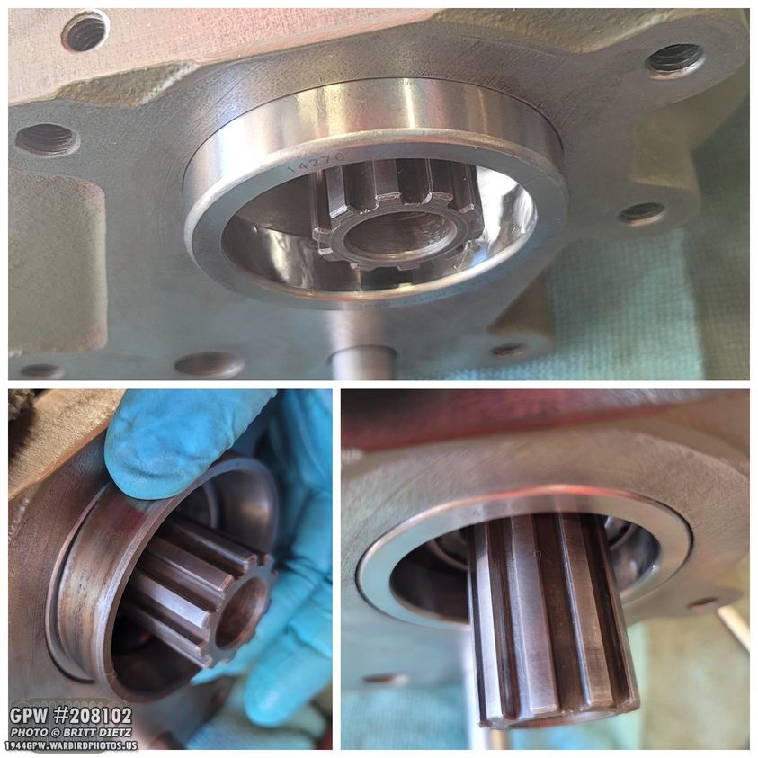
First, take your output clutch bearing (this is a sealed one from Joes Motor Pool), and tape it into this pocket. I heated up that area before putting in the bearing. That expanded the area and allowed me to almost push it in by hand. I just had to do some minor tapping to get it all the way flush in there. After the area cooled down, it was nice and tight in there.
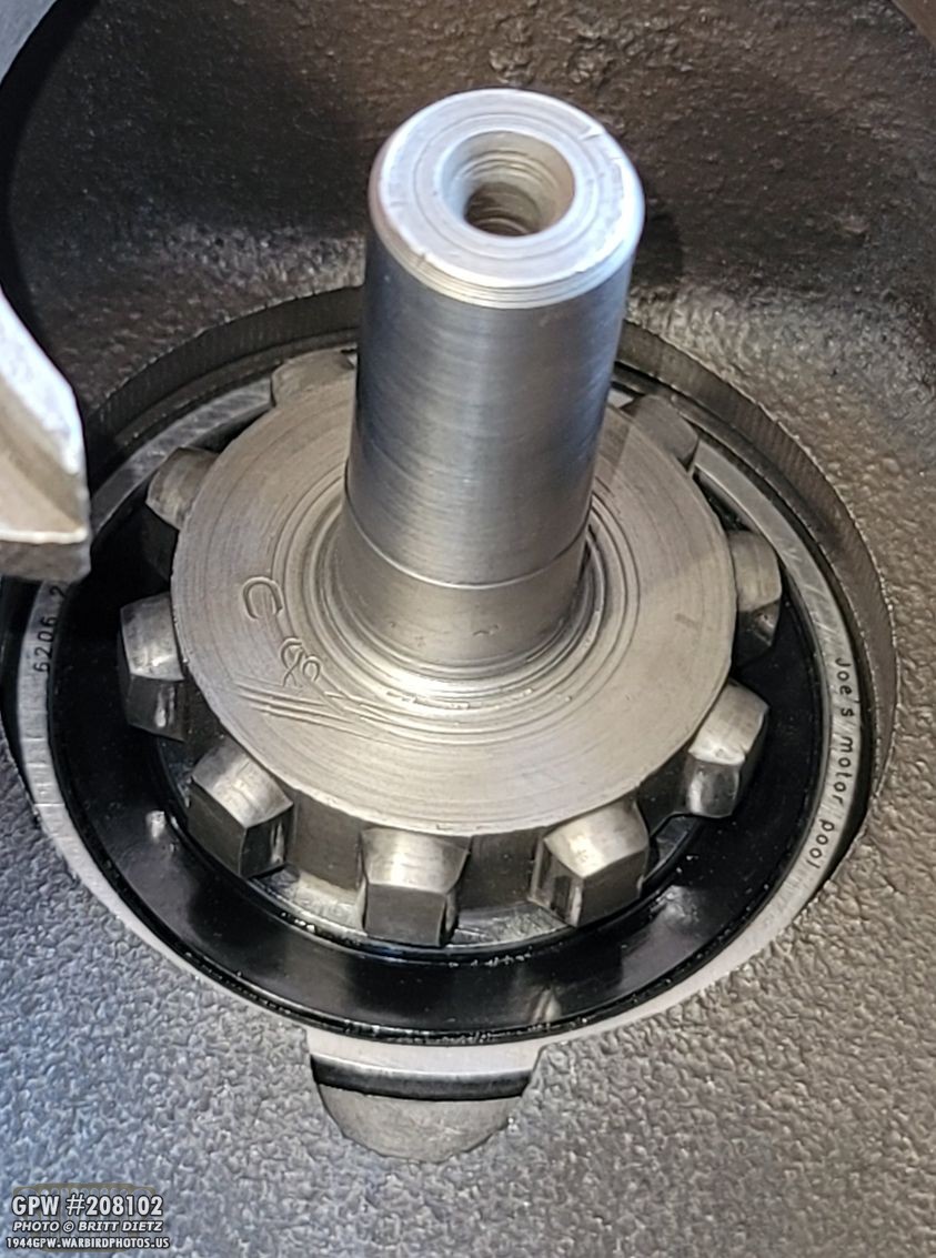
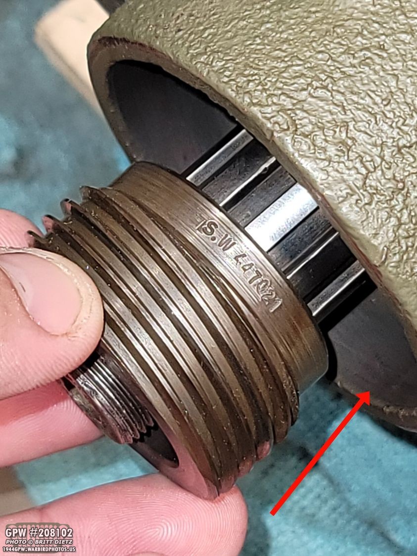
Next, insert your output clutch shaft as shown. Note the F stamp. I was sad to think that this (I hope) would be the last time I see these F stamps.

Now, to lock that bearing in place, you need to add a snap ring. This snap ring can be tricky to get in, and it took me several frustrating attempts to get it in there. You’ll eventually get it, but it might take some time. It’s helpful to use the little cutout area to get the snap ring started.

With the snap ring in place, time to add the 2 wheel/4wheel drive shifter and rod! Note, I took out the output clutch here for the photo.
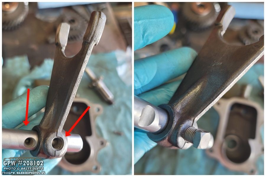
Before you can put in the shifter and rod, you need to do the same as before. Put the shift fork on the rod as shown (with the triangular flange pointing this way). Once the hole in the fork lines up with the hole in the rod, put another one of those block head screws in.

Same as before, use safety wire to lock that screw in place, and make sure you have it tight and snug against the fork. You’ll know if it’s not snug rather fast as it’ll block things from installing in the next few steps.

Now, take the shift fork/rod and put the output shaft clutch gear together (sorry, didn’t get a photo of that) and then place both together into the ouput cover/cap as shown. The output shaft clutch gear will mesh with the teeth on the output clutch shaft.

Before the next step, an important step to do and decision to make! You will need to insert the small pill-looking shift rail interlock into the shaft located here on the opposite side of the shift fork/rail you just put in. This interlock goes between the two shift rods and is what prevents you from doing low gear in 2-wheel drive. Some people will exclude this, which allows you to use low gear with 2-wheel drive. This is a personal preference. It will not hurt anything to leave it out. I drive on flat hard roads, so I use 2 wheel drive in high gear, so I’m keeping it in. Make sure it doesn’t fall out during the next few steps.

In order to do the upcoming shimming, you will need to have your gasket on the output cap as that will make a difference. I got a full transfer case gasket/seal kit from Ron Fitzpatrick Jeep Parts.

Here’s the gasket on. You can come back and put RTV sealer on it later, we’re just putting it on to verify everything.

Now, go ahead and put the output cover/cap onto the transfer case. With that interlock pin in there, it’s going to fight you as you try to get the other shift rod to go through, but keep wiggling it, and eventually, you’ll feel it lock into both of the shift rods. You should be able to then just push till it contacts the bearing race that we put in. Remember that? This is where you will set the depth. Take a rubber hammer and hit the cap on. It will push the race in to the correct depth once the cover/cap is pressed against the transfer case.
Go ahead and torque the bolts to 30 foot pounds. This will ensure that race is pushed all the way to where it needs to be.

Go back over to the otherside we started at. Take the other bearing race and put that on. This time, only put it on about halfway. It’s important NOT to push it in beyond that.

Now it’s time for shimming! Since I already had two shims on, I was given great advice by Roger Smith to add about .030 more shims from the shim kit I got from RFJP. This is where you will want to have MORE shims than you need. Why? Because if you don’t have enough shims, you will need to drive out the bearing race that will be pressed in on this side, and that isn’t easy. I ended up putting an extra .031 worth of shims. If you’re starting with new shims only, start with about .060 worth of shims.

Here’s all the shims on the race. Note how the race sticks other further than the shims.
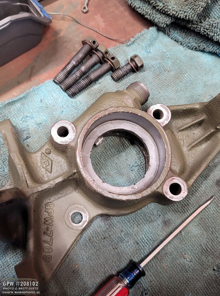
Now, to drive that race in with the shims, you will need to attach the emergency brake bracket. I have the earlier style extenal e-brake, so to make things easier I took eveything off so it’s just the main bracket.

Put the bracket on, and hand tighten the bolts. Do not hammer on the bracket. You will be tightening the bolts instead this time to set the bearing race depth. I used the old copper washers with the bolts.

Because you’re using the bolts to press in the bearing race, you should tighten them in a cross pattern, like so. As with the other side, tighten to 30 foot pounds.
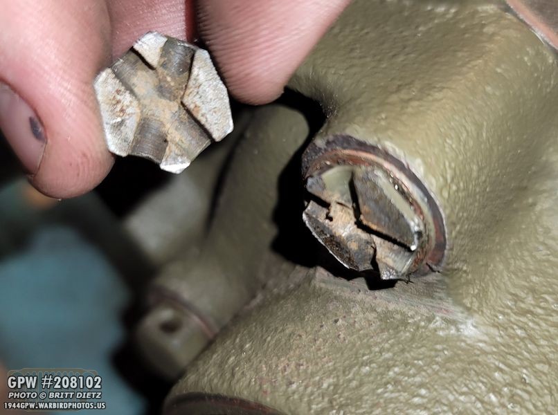
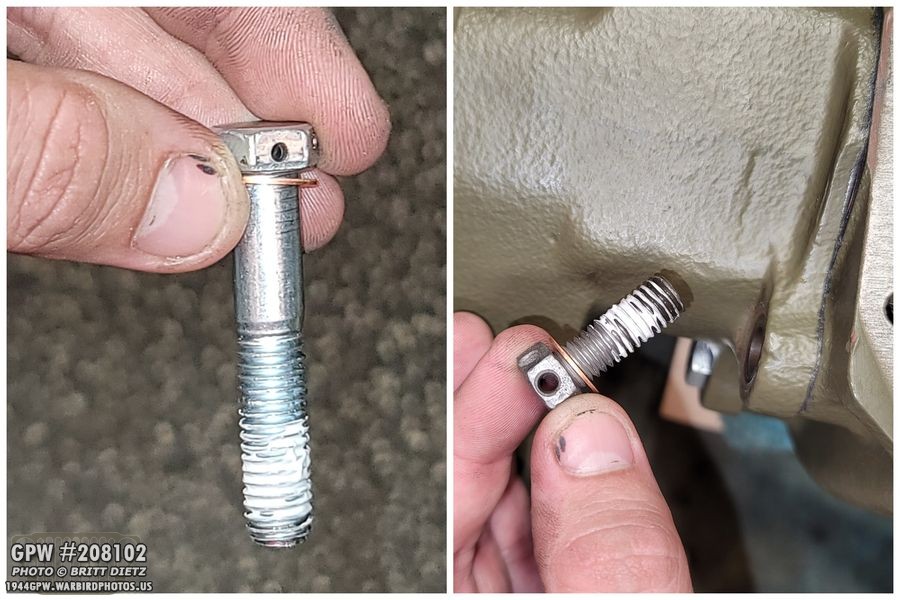
Side note, torquing them to 30 was enough to sheer off one of the heads of the bolts! YIKES! Thankfully, there was still enough of the head that I was able to slowly remove it. I guess these 76 year old bolts have had enough.

Tigthening one of the other ones, I noticed that it just wouldn’t tighten. Strange… so I took it out and looked, it was actually stretching the bolt! Here’s a look at one of the good ones, and the stretched one to compare. Ugh!

I ended up going out and getting some grade 5 bolts of the same length and size. I used a drill (wasn’t easy and ruined two bits) to drill two holes in the heads. I made sure the 16 gauge safety wire fits through.

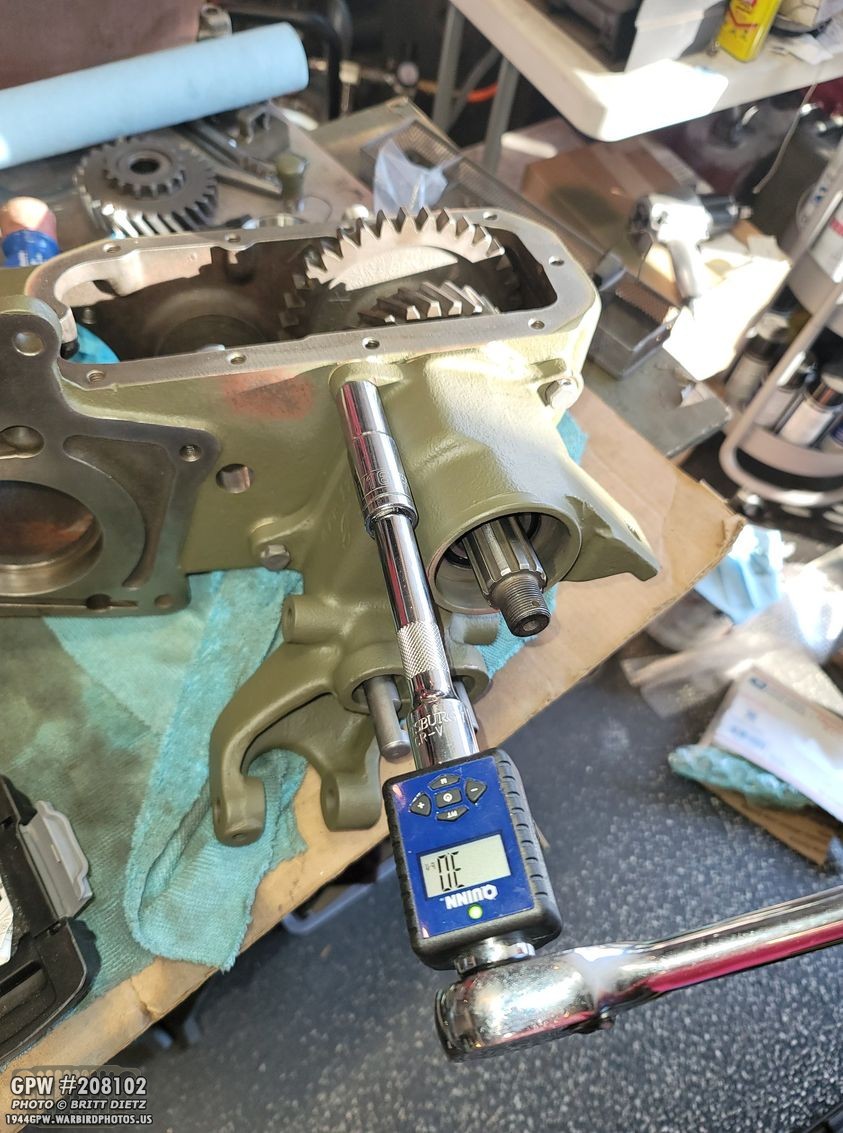
Now I could go ahead and righten everything down. Once torqued, we need to check the play of the output shaft from this side. We’re going to be checking how much you can pull it out and push it in.

To do this, you need a dial indicator. I have it set up so it’s resting on the shoulder where the teeth begin on the shaft. That way I can grip the threads to pull it out and push it in. I got super lucky, turns out adding the extra .031 worth of shim was perfect. I was getting nearly 0 play whatsoever on the shaft. If you find that you have too much play (more than .008 is too much), you will need to add more shims and you’ll have to drive out that bearing race. If things are tight and won’t spin, then there’s not enough play and you need to remove shims.

Again, if you have to add shims to add more play, you will need to tap out the bearing race back to half way. In my case, I found that if I added another shim, it was too much play. So keeping it at the .031 extra I added onto the two original shims was perfect. Once you seal the shims (coming up in a few steps), it’ll add a little bit of play.

This can be a tedious task, which is why it’s better to start with too many shims than not enough. Again, no enough shims means you have to tap out that race, which is difficult. Removing shims just means taking off the e-brake bracket, removing a shim, then putting it back on tightening the bolts again in a cross pattern.
I was just a hair over 0 play, and everything was spinning nice and freely.

Once you get the number of shims to where it works best, get some copper spray gasket to coat both sides. This is a copper based ‘glue’ in a sense, which will seal up the shims from any leaking, and also stick them together. Once you spray them they will get sticky pretty quick. Let them ‘dry’ for about 2-3 minutes, then go ahead and stack them back up. Put the thicker shims on the outsides of the thinner ones.

Quickly put them, while still tacky, onto the emergency brake bracket backside. I used the bolts to hold them in place.

Now go ahead and put the e-brake bracket on and tighten up the bolts in a cross pattern. I went ahead and checked the play one more time after I did this. Now I was getting a tiny bit of play, well within where it should be! (ignore that the 999 gear is installed, we’ll be getting to that in a next.

Now, I already covered how to install a main intermediate gear (the 999 gear) in the case two weeks ago when I was checking to make sure it wasn’t worn. So I’ll quickly go over again the installation. First, put in the new roller bearings into the center shaft of the 999 gear.
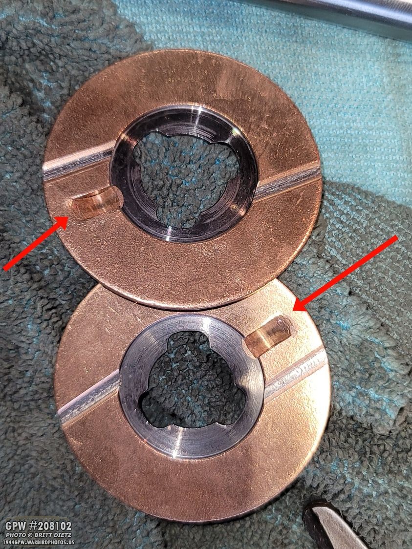
Take the two copper thrust washers, and note the raised notch in each one. They will go into slots on the transfer case.
I used some light grease to hold the thrust washers in place. I’ve heard others use glue to hold them in place as well. This worked for me. I didn’t get a great shot of the slot on the case, but make sure you put the silver side with the notch so that the notch is in the slot.

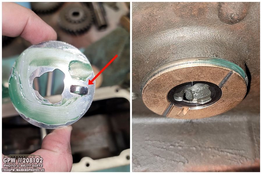
Again, the reason for the grease is to hold these in place as you’re trying to install the 999 gear. Otherwise, like the bottom one without grease in this photo, it’ll just fall off to the bottom of the case.

Here’s how both the thrust washers look once they are stuck on with the super light smear of grease on each. Also, I used the intermediate shaft to help lock one of the washers from falling off.

Go ahead and carefully place the 999 gear in with this orientation. You might knock off those washers a few times, so be patient and careful. You’ll get it! I then went and pre-filled the gear with some oil in the little oil holes so it’ll spin better when I’m testing things.

Now it’s time to insert the intermediate shaft if you haven’t done so already. You might need to pick up the gear a little bit so it lines up with the shaft. You also might need to use a screw driver to move the thrust washers so the shaft can full go through. Make SURE as you’re pushing in the shaft that the slot in the end is facing the threaded bolt hole (bottom photo). You want to be pushing this shaft in from this side only. If you try to do it the other way, it won’t work as the hole on the other side is a bit smaller.

And here’s why the slot needs to face that direction. Once you have the shaft almost all the way in, place the lock plate in and the bolt with lock washer into the hole in the plate screwing it in. This will lock the shaft from coming out.

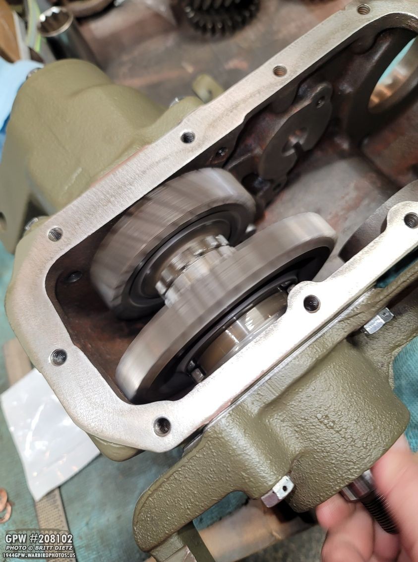
Everything should freely spin at this point, like so! If it does, congrats, you’ve done a GREAT job! All that’s left is to go back and finalize all the bolts and add the gasket to the output cover/cap.

Go ahead and take off the output cap/cover. It won’t mess anything up! Make sure that interlock pin doesn’t fall out! We need to put some RTV on the gasket we installed earlier. Here I’m using ultra black RTV (which is oil resistant).

Put a nice layer of the RTV on both sides.
Put the cover/cap back on (careful of that interlock pin!), then tighten up the bolts. Make sure you add new copper crush washers and put some Permatex thread sealer on the bolts so they don’t leak oil. Torque to 30 foot pounfs again.

Once that’s tight, you don’t need to take this off again!

Now you need to add the poppet ball bearing and spring! Put them on both the shafts on either side. Poppet ball first, then the spring. Then you can screw it down with the large headed short screw (not shown). Do this on both sides. This will ‘snap’ your shifter rails into the different positions (IE 2 wheel/4 wheel drive, and high/neutral/low gear).
To finish up the e-brake side, enter the speedometer drive gear in this orientation. Push it all the way back. Do this BEFORE the oil seal.
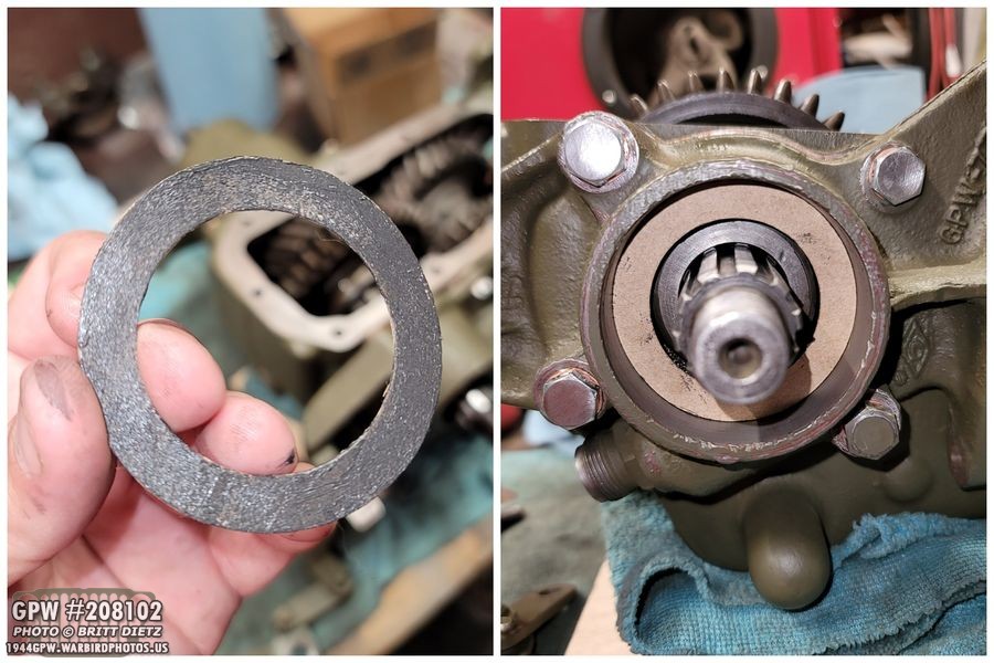
Once the speedometer drive gear is in, you can then put some RTV on the ring gasket and push that on.
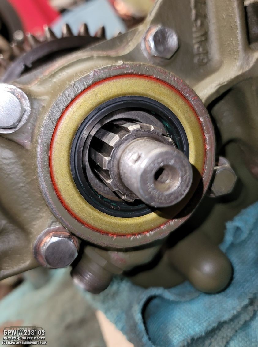
Now you can install the oil seal. Make sure to pre-grease the inside lips of the seal so the yoke, once it’s installed, will run smooth on those double lips. Otherwise, it would rip them up or wear them out quickly. If you haven’t on this side yet, take out each bolt one at a time, put a new copper crush washer on them, put thread sealer on the bolts, and tighten them back up to 30 foot pounds. This side is done for now!

Over on the other side, same thing… put some RTV on the backside of the paper gasket…

Put in the oil seal. The oil seal on this side actually is recessed inward more than the other side, so I used the original oil seal (taking it to my belt sander and running the outside edge along the sander so it won’t get stuck in the shaft) to hammer down the new seal into place. Some people, I’ve been told, put two oil seals here.

Finally, you need to add the tiny oil seals to the shift rods. Pre-grease the inside lips again, and push the seal on till it stops.
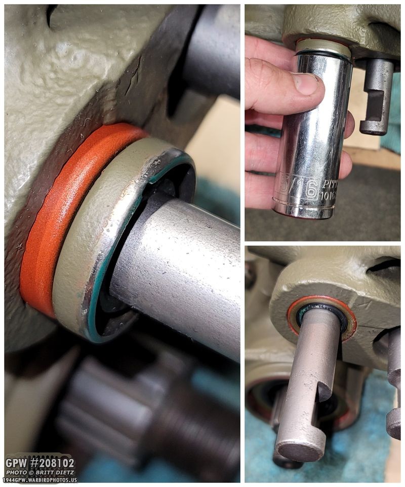
I used the original seals here as well. Since these seals in only a hair, you don’t need to worry about sanding the outside edge of the original seal. I then used a 5/16 deep socket to smack the original oil seal, which pushed in the new oil seal to where it’s just a hair recessed.

Repeat with the other side, and you’re done!

I went ahead and put some thread sealer on the oil pan drain plug, and went ahead and tightened that up.

And wrapping up this week’s update, I went ahead and put on all the covers with stand-in bolts as I’ll be doing another coat of paint, which is important to help seal up everything. Look for that next week along with rebuilding/adjusting the e-brake, mating the T-84 and transfer case, remounting it all back in the jeep and the first test drive! A lot to come, till next week…