 Gears, Gears, and more Gears!
After a successful removal of the transmission last week and then the successful disassembly of the T-84 Transmission, this week I turned my sights to the transfer case! As with last week’s tutorial on the disassembly, this week also has a full tutorial on how to take apart a D-18 transfer case, which appears to be ALL original and never taken apart! I also work on priming and painting the T-84 and various other items in prep for the rebuild!

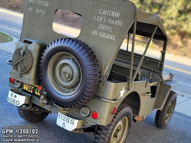
I really can’t wait to take her out on a nice drive like this again, I feel over the last few months she’s been down getting work done more than I’ve been able to drive her! But, it’s all for good as she nears total restoration completion!

Recapping, last week I removed the transmission from the Jeep. During the last two years of restoration of the Jeep, it’s the very last thing that I haven’t restored. Last week I did a step by step of how to remove the transmission, and also how to disconnect the T-84 from the transfer case.

Last week I also did a step by step tutorial on how to take apart the T-84, shown here. I’m pretty certain my T-84 was rebuilt within the last 20 years before I owned the Jeep. All of the gears but one (the clustergear) look newer and don’t have any F stamps on them. The clustergear, however, is date 3/1944.

With the case empty, I sandblasted the case, cover, and transfer case back cover.

I then put the cover back on the T-84 case, put some tissue into the drain/fill holes, masked off the flat surfaces, and put in some long screws (which I didn’t mind getting painted) to hold the cover in place.

I then hit it with @[256477467720803:274:Ron Fitzpatrick Jeep Parts] Red Oxide Barrier III spray paint, which dries nice and fast. I then used a scotch pad to scratch it up. Then, it’s time for the VHT Ford Gray engine paint!

I LOVE this VHT Ford Gray paint. It goes on thick, dries in seconds, is super durable, repels grease and oil, and looks really sharp. This T-84 case hasn’t looked this good since it left the factory in 1944!

After wire wheeling the crossmember (which was a lot of work), I cleaned it off and it’s ready for paint!

Same with the shifter canes and the T-84 support bracket.
This is one heck of a unique F stamp on the T-84 support bracket. I’ve yet to see one quite like this.
Here, the main shifter cane has red oxide primer paint.

And then the two transfer case shifters, the T-84 support bracket, and the transfer case rear cover plate.

The next day, I was able to get three coats of 33070 OD Green paint on them via @[256477467720803:274:Ron Fitzpatrick Jeep Parts] gallon paint with the spray gun. Love that paint with Xelene thinner, it dries so fast and goes on so well!

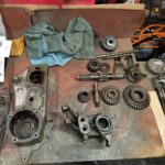
I’ve had the various gears soaking in parts cleaner. They come out nice and clean, dry, and ready for reinstall!

I also cleaned up the transmission main gear retainer. Almost looks brand new on the bottom side!
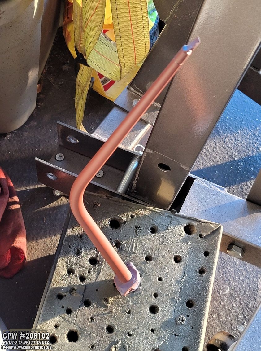
To remove the bearing from the input shaft, you need to remove the snap ring holding it on. That was quite the feat to get off. It took forever to do, using three screwdrivers to slowly pop it out. You’ll get frustrated with these snap rings, but just keep trying and have patience! After the snap ring was off, I could then use my bearing puller to pull it off the shaft.
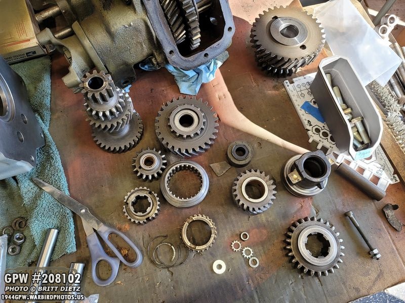
That’s a lot of gears! All ready for reinstall. Just needs the replacement bearings, bushings, and snap rings! I’ll start the rebuild next week!

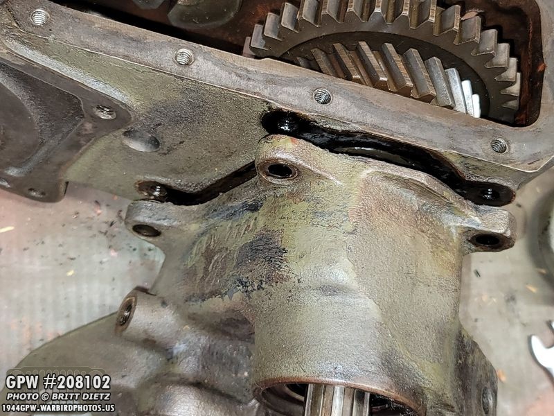
Moving on to the transfer case first step is to remove the 999 intermediate gear. To do this, you need to be able to get to the bolt and lock plate on the back of the transfer case, so you need to remove the emergency brake, if you haven’t done so already. I have the earlier style external e-brake, but the same applies if you have the late internal e-brake.
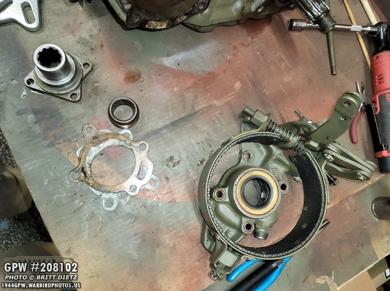
I’ve covered how to remove the e-brake assembly from the transfer case earlier in 2020 when I restored it and replaced the brake bands, so I won’t go over it this time. But it’s a pretty easy removal. Take the castle nut off, pull the yoke off, undo the safety wire on the four screws holding it to the transfer case, then pull it off.
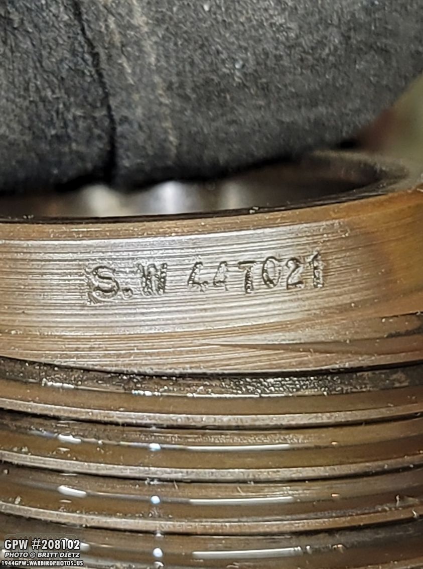
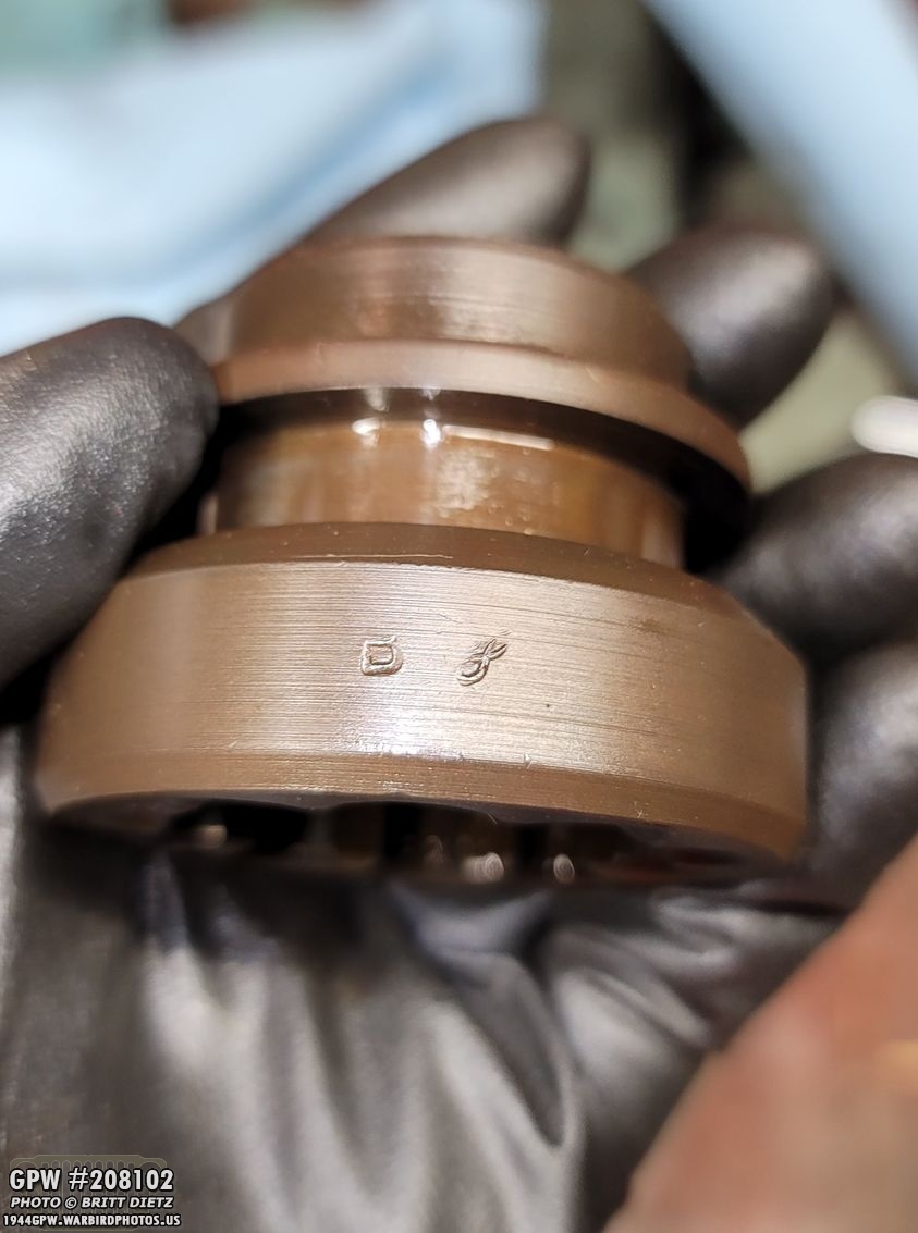
One thing to note, the speedometer drive gear (which will be removed once you take off the e-brake), appears to be original with a Stewart Warner stamping in it.
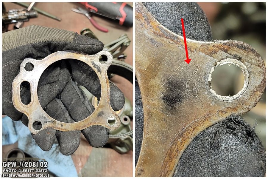
There were two shims underneath the e-brake for the transfer case, one a thick metal shim with a F stamp on it, and a thin one under that shim. I’ll keep these as when I go to shim it later, I might reuse one or both of them. The backlash was pretty bad on the transfer case, so I will be changing the shims either adding to or removing them.

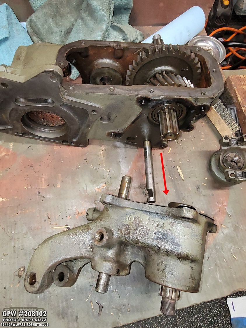
With the e-brake gone, you can now access the bolt and lock plate. (ignore the fact the T-84 is still attached, this was shot earlier).

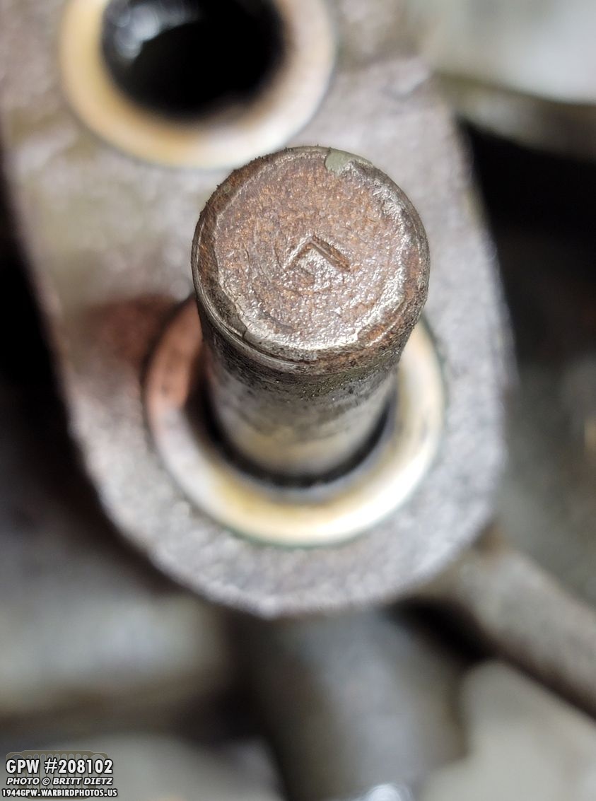
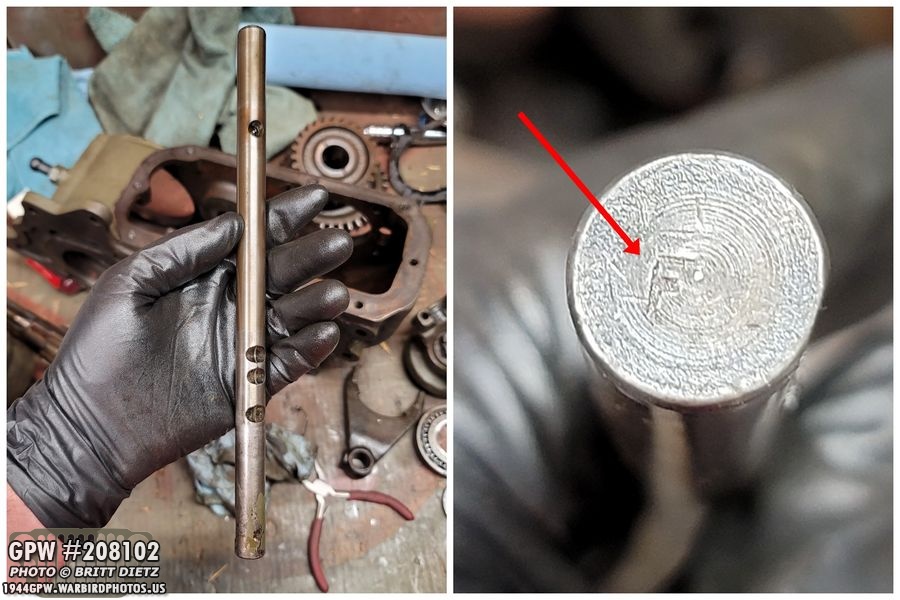
To be able to remove the intermediate shaft (which has a F mark!), you need to unscrew the bolt (red arrow) which will then release the lock plate underneath it locking the shaft in.

This is the 999 intermediate gear, which is a very important and very expensive gear to replace. I was holding my breath that it was in good condition. At this point, I had no real idea the condition these gears in the transfer case are in. Are they all replacements? Are they all original? Are they a mix? We’ll soon know!

With that lock plate out on the back, you can then drive out the intermediate shaft towards the rear (as shown). Once it’s out (and it might take some effort if it’s tight on the 999 gear, which mine was), you can just lift out the 999 gear.

Taking a look at the gear, it’s in really good shape. No pitting, teeth look good. (note, looks like pitting but that’s oil on the smooth surface).

And it’s original! A nice F stamp on the 999 gear!

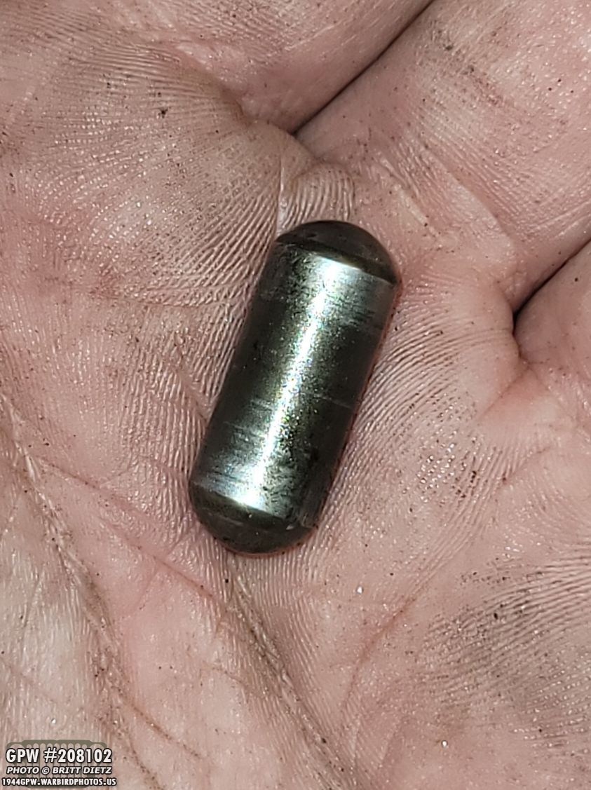
Don’t be alarmed with a ton of bearings fall out of the 999 gear. I was lucky and the bearings stayed with their cage (top of the photo). The two thrust washers will also fall into the case when you take out the 999 gear. I’ll replace these as they look a little worn.

I’ll replace the unique bearings for the 999 gear as well, while one looked in good shape, the other has some dings and dents in it.
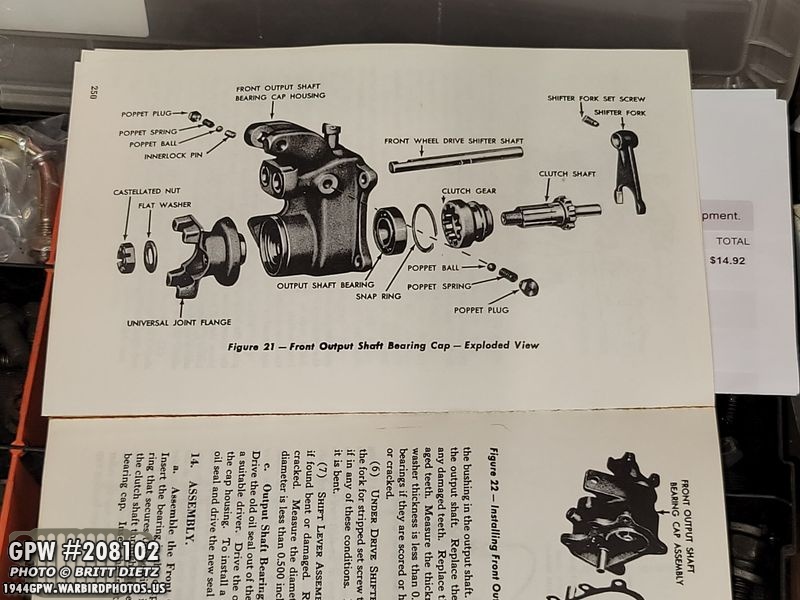
Getting started on the transfer case, it’s really helpful to have a TM manual for the power train with you, as the break downs come in handy!

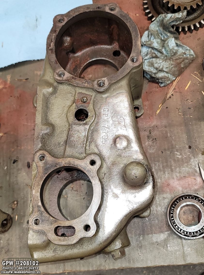
First up, the front output cap/cover!

To get started, you need to remove the cotter pin holding the castle nut onto the front yoke.

I’m pretty sure the nut hasn’t been removed in 76 years. It was pretty much welded on. I used my impact air gun (up to 120psi), I tried brute strength with a breaker bar, I tried heating it up to expand it, BP blasting it, heating it then rapidly cooling it… nothing. I made sure to brace it with a 2×4 and a piece of scrap metal to stop the yoke from spinning.

It took a long time, but after really giving it a long go with the impact gun, it finally spun loose. I was honestly afraid the whole disassembly would come to a grinding halt with this darn nut.
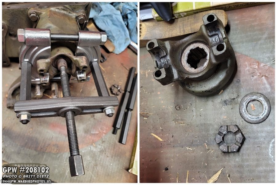
With the nut off, I could use my bearing puller to pull off the yoke, which came off much easier than the nut!
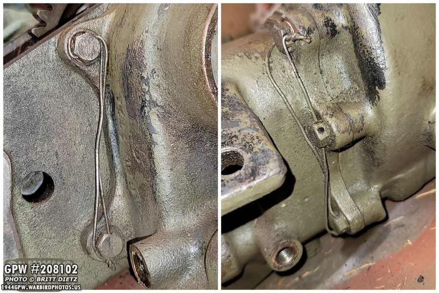
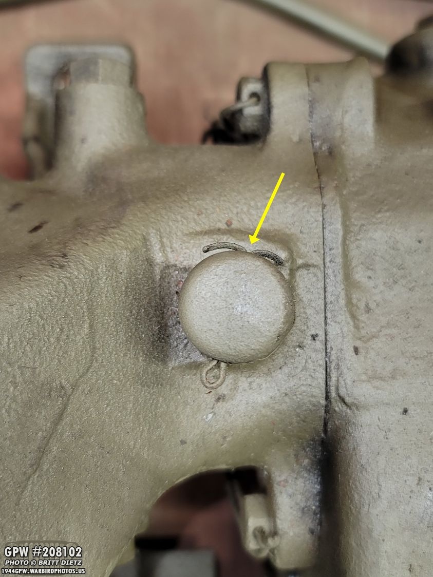
Before going on to the next steps, I make sure to take photos of the safety wires in the bolts connecting the front cap cover to the main transfer case. When I reinstall those screws later during the rebuild, I’ll need to put the wire back on the bolts which will lock them in place and keep the bolts from spinning.

Now, you’ll need to remove the shift rod poppet plug bolts on either side of the main cap.

Behind those small bolts are springs, which you’ll need to use small needle nose pliers to get them out.

And then behind the springs are small poppet balls. Tilt the entire transfer case over and the balls will fall right out.
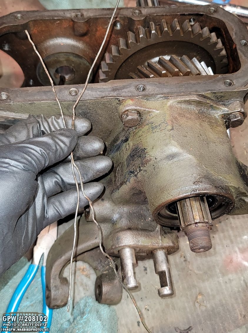
Now you can remove the safety wires from the bolts.

And then remove the five bolts holding the cap to the main transfer case.
They didn’t want to come apart at first, but a few soft taps of the rubber hammer and it started to split. It takes a bit of wiggling to get it to start coming apart.
Pull away from the main case, giving it some slight twists as you do. The long front wheel drive shaft will stay with the case. The cap may get hung up on it, but just wiggle and rotate the cap around and it should come off.
You’ll also find the shift rod interlock (that keeps the two shafts aligned) will probably fall out. Don’t lose that!
I noticed as I pulled the cap off, that the other shaft rail (underdrive shift rod) has a partial F on it.

turning the front cap over, this is what you’ll see inside. The large fork is being held on to the shaft with a locking bolt (red arrow) which you will need to unscrew. But, there’s more safety wire (green arrow) holding it in place, so you’ll have to either snip that off or carefully unravel it and feed it through the bolt. Then the bolt will freely come out.
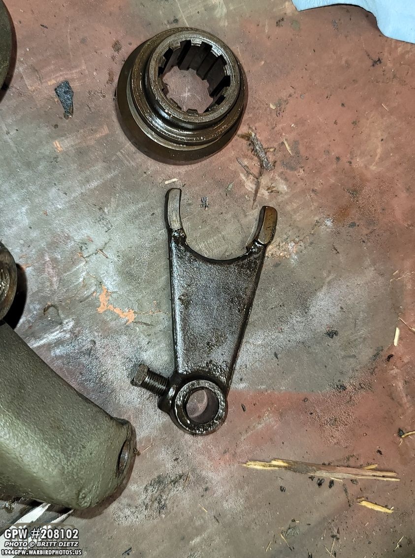
Once the bolt is out, you can slide out the fork from the rail, and also pull out the output shaft clutch gear (top).

You can now pull out the underdrive shaft rod out from the front.

To get the output clutch shaft out with the bearing, you need to remove another snap ring. This one ended up being easier than I thought. I rotated the snap ring (blue arrows) so one of the ends (yellow arrow) was in the little but out area (red arrow). I was able to then pull that end out of the little channel it sits in, and slowly start to pull out the ring till it popped out.

Here’s a look at that snap ring. It came out so easy, I can reuse it!

After that, you can tap out the output clutch shaft (from the outside in).
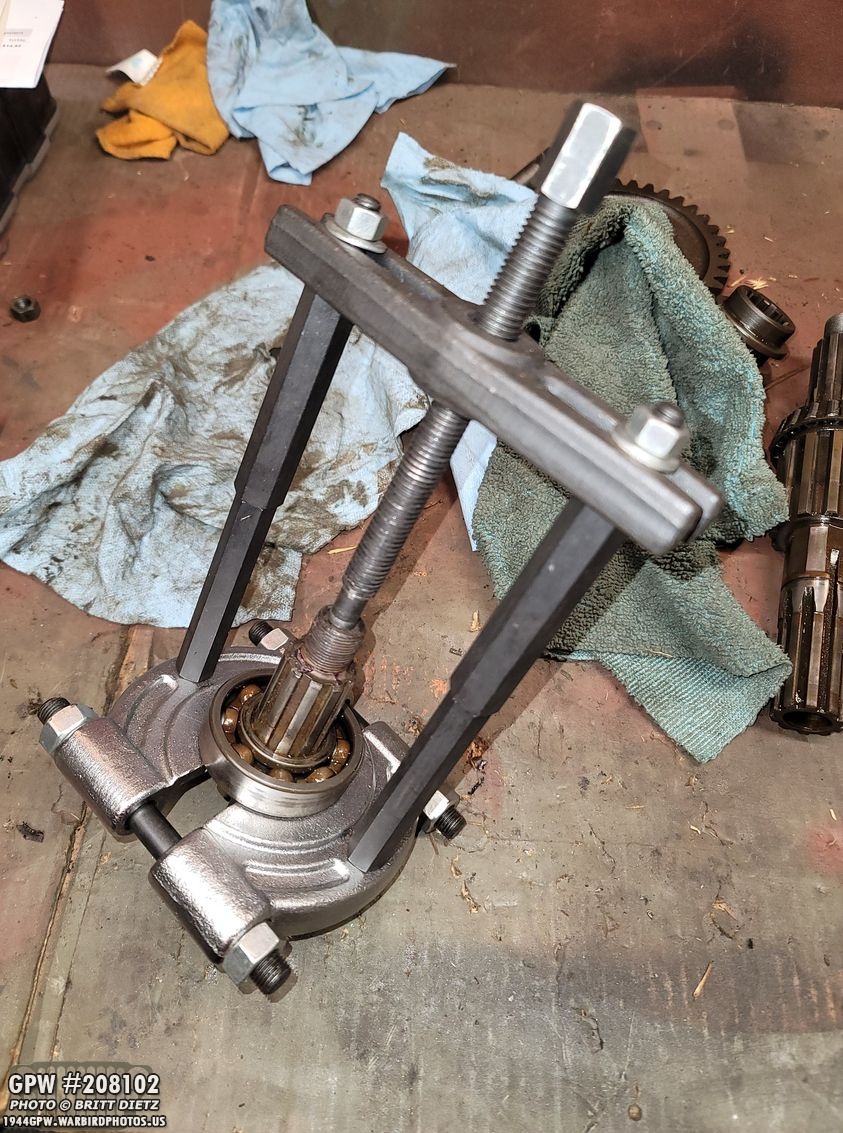
I used my bearing puller to get the bearing off the shaft.

The last step for the front output cap is removing the oil seal… which for me was in there REALLY good. Using an oil seal puller just tore up the seal bending the metal. So I turned to tapping it out from the inside with a punch, which slowly worked until it finally came out. I do believe this is an original oil seal, so it’s been in there for 76 years!

And don’t forget to remove the two small oil seals where the two shifter rails come out. These came out easy with the oil seal puller.
Last little item to remove is the breather cap and tube. To do that, remove the cotter pin and pull off the cap.

You can then use a small screwdriver in the cotter pin holes on the tube and just screw it off.
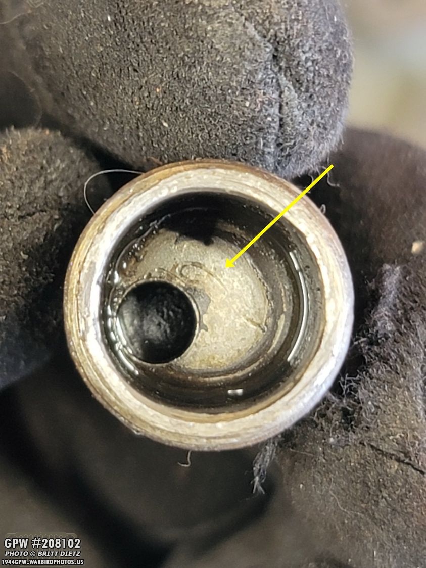
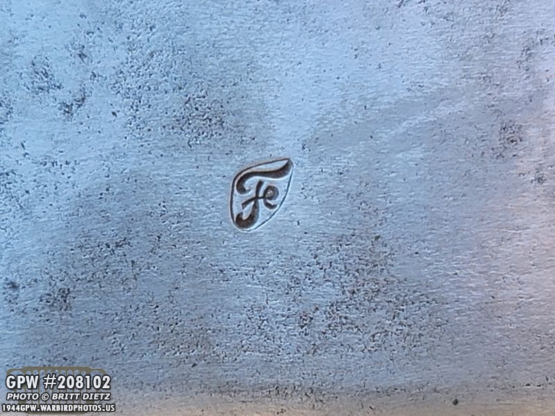
There’s actually an F stamp inside the tube! Pretty neat to see.

Now on to the main transfer case for the final gears and shaft. You can’t do much of anything until you remove a snap ring… and you can’t remove that snap ring while the shaft is still in place. So take a rubber hammer and hammer the whole shaft towards the back until the bearings on either side of the shaft come away from the cups (as shown). It won’t come all the way out since the gears are still on, but it will give you remove to get that snap ring out.

And here’s where the small snap ring is located. It can be a pain to get off, but for me it actually went pretty easy. I used a snap ring spreader and a small screwdriver to pop it out of the groove and onto the shaft.

Now you can pull out the output shaft which will leave the gears loose inside the case as they slide off.

You can take all the gears but one off. The output shaft sliding gear will still be connected to the second shift fork, which is connected to the long front drive rod. Just like the other shift fork, you need to remove the safety wire and then unscrew the bolt to loosen the fork on the rod.

Here’s a look at that safety wire and the bolt on the fork.

Once that’s removed, you can simply pull out the long rod, which will then make the fork fall away from the output sliding gear, which you can then just pull out (not shown in this photo).

There will be a bearing cup still in one of the holes, so make sure to punch that out.
And you should now have an empty transfer case!!
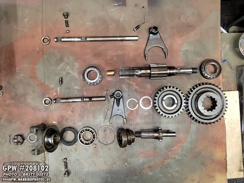
Here’s a look at all the gears, shafts, bearings, etc that make up the transfer case in the correct order and layout. Now that everything is out, let’s inspect all the items and see if the items are new or original…

I can’t find an F stamp on the front output yoke, but I do see this stamping on the inside. I will have to wire wheel it to see if the F stamp is covered with multiple layers of paint.
First gear up, the output shaft gear… and it has an F stamp!

The output clutch shaft bearing appears to be made by Fafnir, which I’ve never heard before.

Both the output shaft roller bearings are Timken with Bower cups (not shown).

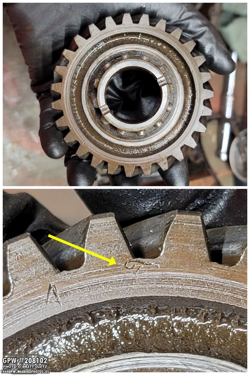
The output shaft sliding gear has TWO F stamps! A small one on the front, and a large one on the back!

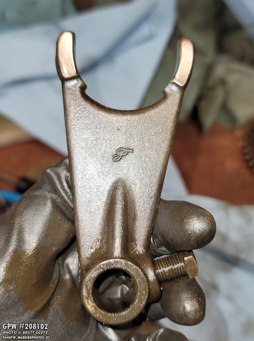
The sliding gear fork doesn’t have a fancy F stamp, but it has an F plus a GP number!
The other front wheel drive shift fork has a nice F stamp!
And as mentioned both the rails/rods have plain F stamps on the end.
The output shaft clutch gear has an F stamp on the side.
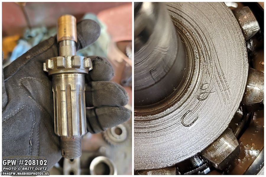
The output clutch shaft has a F stamp on the gear side.
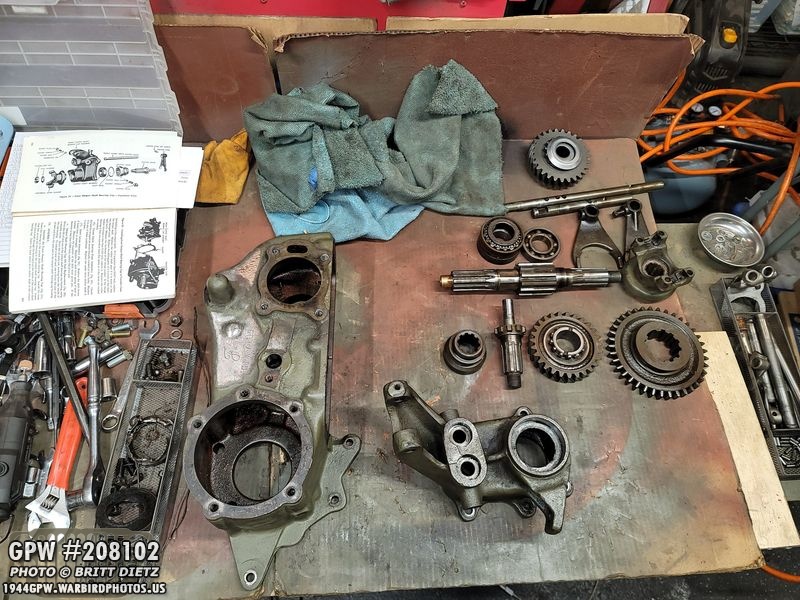
So, after looking at everything I’m convinced that this transfer gear is not only original, but it’s never been taken apart in 76 years! Pretty darn awesome, and it appears that it’s all in great shape! Now comes the next step… cleaning it all up!
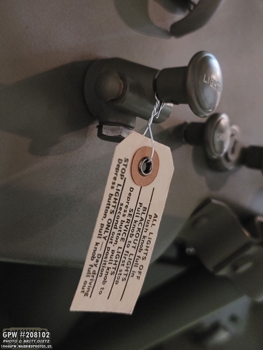
As I wrap up this week’s update, another project I’ve finished which I’ll cover in a future update is recreating near-perfect push-pull light switch hang tags! These are nearly identical to the originals down to the font and materials used. I hope to offer a small run of these for those interested in the near future!
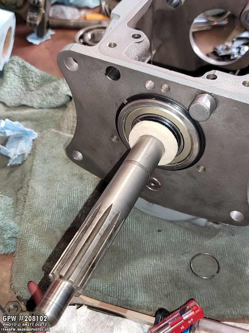
Next week will see the restoration of the transfer case itself including painting, and starting the rebuild of the T-84 (shown here, a preview!).
So that’s it for this week! Two great weeks of work taking apart the transmission and transfer case! Overall, it’s a lot easier than I was expecting and not nearly as difficult as I thought. Hopefully, once I get parts I can get all this rebuilt and put back in the Jeep this month so I can take her out for a spin again! Till next week…