 Hood work, Firestone Spark Plugs, and Rear Axle work – Part 1!
This week’s update will be a two part post once again! I got quite a few things in the mail to continue my ongoing quest to correct post-war things on the Jeep, got more radioactive Firestone spark plugs, worked on the GPW hood including fixing some stress cracks, and fixed a stripped bolt hole in the rear axle hub with a Helicoil kit in this first part!

Getting closer and closer to that moment when the CJ rims and axles are removed and the GPW axles, combat rims, and Firestone tires are added! Hopefully by next month if all goes well! This past week was full of fun activities on various projects!

MAIL CALL! Another shipment from Ron Fitzpatrick Jeep Parts! I love the little spray can Red Oxide primer, but when I go to painting the GPW hood with primer, it would take forever with the spray cans. The gallon version will go much faster with the air gun and cover better! I did get another touch-up spray can of 33070 OD Green for various things. Can’t have enough of those! The rest of the items are a combination of parts for the axles themselves, the spring system when I take them apart to replace the axles, and some shock bumpers. I’ll get to most of these items in these two updates for this week.

SECOND MAIL CALL! After realizing that I missed a few items, I made a second order to Ron Fitzpatrick Jeep Parts. Again, more items for the axles (the brake lines in particular) and a new heat riser spring, which I’ll explain in Monday’s update.

Moving on, so a few months ago, I stumbled across a seller at a flea market who had original NOS Firestone F-40 spark plugs. These contain Polonium, which is radioactive! But, the half-life for them is about 138 days, so there have been over 200 half-lives of the Poplonium, meaning they have less radiation than you just walking outside. The seller only had 3 of them in their original boxes wrapped in wax paper, so I got all three for a steal, but I needed a whole set, so I waited an entire month to see if he had more at the next flea market (which he said he had). Sadly, he sold out of them before I even made it to his booth!

But, he asked me to text him later, and sure enough, he found 5 more! He sent me all 5 in the original carton (pretty cool!)

I love they are all sealed in their original boxes. I was hoping he would have a ton of them left, as I have several people who wanted a set for their Jeeps. With 5, I plan on using one to complete the four in my engine, and the other four I’ll keep as spares in case any fail.

Here’s a look at one of the spark plugs, fresh out of their wax paper.

They are dated 1942, as best as I can tell from dates on the wax paper, and are pre-gapped to .40. Jeeps need spark plugs set to a gap of .30. So I took my feeler gauge and carefully bend the curved electrode inward to reduce the gap, shown here with a .30 feeler gauge.

After removing the last modern Autolite spark plug, I wanted to show the difference between the Firestone F-40 and the modern plug. A pretty significant difference in design.

Here it is installed in the #3 spot!

You can’t really see them well with the rain shields on, but you can just see the Firestone and Polonium underneath.

And there we go, four 1942 Firestone F-40 spark plugs working beautifully in my Jeep! I still swear the engine is working better since I added these.

Focusing on one of the things I got from Ron Fitzpatrick Jeep Parts, a set of four Jeep shock bumpers. These are large rubber bumpers with a metal base that attaches to the frame and, in case of extreme rock crawling or over-weight in the Jeep, they will stop the shocks/axles from getting smashed into the Jeep tub.

The shock bumpers currently on my Jeep, in green here shown taken off, are actually from a Korean-War era M38 Jeep. Someone added them at some point in the Jeep’s life. Here’s a look at the difference with one of the correct WW2 style bumpers (see next photo as to why it’s painted red)

There’s been debate on if the WW2 shock bumpers were painted, or just the metal base painted and the rubber left black with overspray. I’ve seen several GPWs with them fully painted OD Green, so I decided to go that route, but first I scuffed up the rubber and put some red oxide primer on.

I then used a scotch pad to scuff the primer, and painted them with three coats of 33070 OD Green like the rest of the Jeep. They are ready to be installed! That’ll be featured in next Friday’s update.

I’m not above admitting when I’ve made a mistake, and here’s one that might help someone out there. I was having an issue since I installed my Joes Motor Pool Carter WO carburetor of the accelerator getting stuck momentarily when pushing down, forcing me to push a little harder to ‘break free’ of the momentary pause. This concerned me, as it was tough to drive at slower speeds because it would catch. I started to investigate and figure out what was going on…

At first I thought it was the linkage going to the pedal. Maybe it was smacking against the body tub. Maybe I needed to adjust it. So I adjusted the screw going from the carb to the linkage and made it further away from the carb. No change, still stuck. UGH! I checked the carb itself to make sure the butterfly flaps weren’t sticking, nope… smooth as can be. So what was it?

Well, the problem was right in front of me… perhaps you can see it in this photo? I’ll give you a moment to look…Did you find it? I realized what was going on after looking closer at the carb. I had put the throttle wire on the OUTSIDE of the carb linkage. That spring looking cover is the throttle wire. See how it doesn’t go into that open area to the right of it? So when I would push on the gas, the carb linkage slides up the throttle wire, and since the throttle wire was bending outwards to go around the linkage for the carb, it was causing friction and the linkage was catching on the wire. DOH! Total user error.

Here’s after I took out the throttle line and put it correctly on the inside of the carb linkage… no more sticking! Nice and smooth like it was. WHEW! It was a pretty dumb moment when I realized it, but at least it’s fixed and not a serious issue.

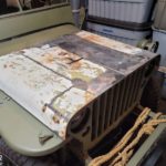
Moving onto the ongoing hood project… last month I picked up this original early GPW hood from a Jeep swap meet (among other things I’ve covered in previous updates). My original hood is too far gone to repair, with a permanent sag in the hood and major cancerous rust. It will be a wall decoration, so I have an MD Juan repro hood on the Jeep right now. I wanted an original GPW hood to replace the repro one, so I picked this one up for an amazing price.

Last week, I started to wire wheel all the paint off a section at a time. I’ve been trying to reveal the original numbers on the hood, but that’s proved difficult, so I’ve been avoiding removing the paint from those areas until I figure out the best way to recover them.

This week, I started on the inside. You might be thinking… why not just get it sandblasted? Well, I don’t have a large portable sandblaster, and the quotes I’ve gotten from local places are way too expensive for just a hood… so wire wheels, nylon wheels, etc bound I go!

It’s been fun discovering some cool original details along the way, like this very sloppy (and HUGE) section of tinning for the radio suppression bond strap on the grill where it contacts the hood.

And here’s the other side, also a HUGE section with the tinning. Someone was just quickly applying it that day!

To give you an idea of just how big they are, here’s a look at both with the handle of my hammer.

The welded on capture nuts where the body tub cowl to hood bond straps go also had a lot of tinning, as shown here.

And here’s the other side. I’ll mask off a square area around the holes so the tinning is left exposed.

After about an hour’s work, one half of the inside is completely wire wheeled! It’s a lot of work, but it does feel rewarding when you can step back and see how nice and shiny it looks. There are little spots of rust that can’t be removed, but they will be painted over and not visible.

I then started on the other side, but it was getting dark, so I decided to call it a day. I’ll be continuing the wire wheeling this weekend if it doesn’t end up raining.

Going back to the hood numbers, here you can see the remnant of one just barely visible. Now, I’m not using the numbers since I’m using the numbers of my Jeep (in an update from February I documented how I found the original hood numbers on my original hood via wet sanding). Getting the numbers on this hood is just for fun reference and documentation, nothing more. So I’m not fully invested in putting a crazy amount of work into it. The problem is that white flaking paint you see. It’s thick, seems to be almost hard as a rock, and it will NOT sand. Even 60 grit sandpaper wet/dry will barely sand it. I can get through it with the wire wheel, but the second it breaks through, the wire wheel goes through the thin bottom layers of original paint. So I’ve been debating if it’s worth all the effort to get the numbers to which I’ll take some photos, say ‘that’s cool’, and then remove them off.

Moving on with the hood, I decided to go ahead and start fixing the problems with the hood. First was this large broken section on the hood hinge. Thankfully, it was a clean break so it should be an easy fix.

After wire wheeling the area clean, I used my welder and did a quick welding job on both sides. Keep in mind, I’m a beginning welder with some practice, but I think that wasn’t too bad!

After using the flap disk, it came out looking like there was never a crack there! Perfect! Proud of myself on this one.

The more difficult (and serious) problem was where the middle channel goes over the outer channel on the passenger side. As you can see, it’s coming away causing the hood to bend outwards. I didn’t realize at the time, it was separating on the bottom as well via a crack that you can make out in this photo. Also, the spot weld to the right on the bottom of the channel had broken.

So, first thing I did was to use a C clamp to keep the channels flat with each other. I then used a strap rachet to pull the hood back together so it wouldn’t flare out.

I then did some ugly tap welds just to hold it in place.

Roger Smith had mentioned that I should do a ‘button weld’ from the channels to the hood. What that entails is taking a 3/8 drill bit and drilling through both of the channels (as seen here) but stopping before you drill through the hood. Then I took a thin wire wheel and cleaned up the area of exposed hood. The idea is that you start in the center of the hole and travel clockwise in a circular motion expanding the radius each time till you fill the entire hole with weld. This holds the channels to the hood with a very strong weld.

Sadly, I forgot to take a photo in my excitement after welding it, so here’s the ‘after’ photo once I took the flap wheel and made it smooth. That channel isn’t coming away from the hood anytime now!

I ended up doing it to the bottom as well, just after I took this photo. It was at this point, I noticed that crack and realized I would have to fix that as well along with the broken spot weld to the right.

Again, when you get some momentum, it’s hard to stop. For me, it means forgetting to take photos! Ha ha. But here’s after both button welds on the left channel, fixing the crack, and fixing the spot weld. It was REALLY difficult grinding down those areas as they were right along edges, so what you’re seeing here is JB Weld Steel on there so I can smooth things out a bit. Once I sand that down and paint it, it should look flawless like the other side!

I also noticed a small stress crack on the driver’s side of the hinge which I quickly tapped and ground smooth (shown here after I fixed it, again… sorry I forgot to take a photo).

The end of the channel on the driver’s side blew through when I was wire wheeling as there were some rust spots that were bad. I tried to weld them, but the channel metal is so thin, it just blew it out every time even on the lowest settings my welder will go. So I gave up quickly, not wanting to make more of an issue, and just filled it with JB weld steel. I’ll sand that smooth as well.

Inspecting the hood further, I found another stress crack, this time near the passenger side’s front lip.

This time I made sure to get a shot after welding. I welded both sides.

And grinded smooth! What crack you say?

And I found yet another stress crack, this time in the very front middle where the seams of the hood come together.

Quick tap of the welder…

Crack-be-gone!

With the issues fixed, I decided to go ahead and do a test fit on the Jeep to make sure everything was good. With my girlfriend’s help, we carefully removed the MD Juan hood and put it on.

It’s GREAT to see a F stamp on the hinge again! I’m also using the correct style recessed head bolts found on GPW hinges. I didn’t bother with the outer bolts as they hold the bond strap.

Moment of truth, I shut the good… perfect fit! A little too perfect, in fact, and I noticed that the hood is still a little too bend outwards on the outer edge where the hood catches are. You can see on the lower left next to the passenger side headlight where it flares outwards too much. I’ll have to heat up the metal a bit and bend it more inward once it’s back off.

One thing I wanted to do was also figure out where the grill bond straps would make contact with the tinned areas on the hood when it’s closed. That way, I could mask off a square area where it contacts. I put some water-based acrylic white paint on the top of the bond straps (easy to wash off).

Then I closed the hood and pushed down on it to make a good contact.

Lifting the hood back up, success! You can see the white spots where the bond straps touched the hood. I’ve since let the paint dry (easy to remove) and this weekend I’ll mask a square a bit bigger than that area with the paint so that when I do prime it, it stays tinned silver.

So the other big project this last week was the rear axle. It’s come a long way, and if you’ve been following along the last few weeks you know it’s been an up and down battle with this darn axle. In short, these original 1943 GPW axles were given to me for free, but there has been a whole heap of issues with the rear axle. For the last 10 months, I’ve been taking both the front and rear axles apart and slowly restoring them. This rear axle had a spider gear explosion, at some point, severely damaging the housing, pinion, ring, and carrier. I’ve since bought an NOS GPW ring and pinion set, and got a replacement GPW carrier. The housing has also been fixed.

Last week, I installed the bearings and racers for the rear axle drums, then installed the drums on the axle. I then installed the washers and axle nuts. But I noticed something when test fitting the axle shafts… one of the bolts never fully tightens, it just spins. After inspecting the hub, shown here, I realized that bolt hole was severely stripped. It’s the hole with the goldish color on the 4 O’Clock position.

I could have just put some lock tight in there when I was all done and buttoning up the shafts, but that would be a one-time deal that would need to be cleaned and re-done each time I take the shaft out. I wanted more of a permanent fix. I decided to give a go at a HeliCoil fix. I’d heard about these being used on everything from engine stud holes to transmission bolt holes. I got this kit, 3/8 size, from Amazon. Comes with HeliCoils, a 25/64 tap, and a tool to place the HeliCoil in the hole. What you basically do is drill the hole larger, tap it to the larger size with new thread, then you screw in the HeliCoil which acts as a reducer giving you 3/8 thread.

What you’ll need is a drill (25/64 bit for the 3/8 bolt hole size), the kit tap/install tool/HeliCoil, a tap pry tool, and some tape.

The tape is to cover up the other holes and the exposed inside shaft so no metal debris get in there.

I also had a turkey over tray underneath to catch all the metal shavings.

To make sure I don’t drill too far, I put one of the bolts into one of the axle shafts and see how much actually goes into the axle hub. I then marked that on the drill bit with blue painter’s tape. Once I reached the tape, I knew to stop.

It is imperative that you get the drill as straight as possible. Thankfully, it made a perfectly straight hole. Next, you put the tap in and carve out the threads shown here. I used some cutting oil to help it go smoothly. The tap worked amazing, with hardly any resistance, but you can see it’s making thread by the metal debris. I got the threads started, then turned the tap out.

I then marked the tap with tape, just like the drill bit, to make sure I didn’t go further than I needed to.

I then used a pipe cleaner, the shop vac, and compressed air to REALLY clean out the hole of any metal debris. There was a LOT in there.

All clean with nice new 25/64 thread!

Next, I take the HeliCoil and put it on the end of the special tool. See that curved end of the HeliCoil? That is grasped by this tool. After a certain amount of torque, it snaps off once the HeliCoil is set.

With the crisp tapped threads, the HeliCoil went in nice and smooth. No tools needed to help the install tool, I was able to spin it until the tab broke off. I used the shop vac to suck out the tab.

Here’s a look inside, you can see the HeliCoil in there reducing the 25/64 to proper 3/8 size. But the real test… does the bolt tighten?

Success! Tightens just like any of the other bolts! So that’s how you fix a stripped bolt hole.

Some of the items I got from Ron Fitzpatrick Jeep Parts, I was originally going to use my rear CJ axle’s brake bracket (it’s identical to the WW2 design), but I noticed the holes were elongated, so I decided to get a new one. I was then able to test fit the brake lines with the tri-connector.

Here’s a quick test fit of the brake lines on the rear axle with the new bracket, and also a strap holding down the brake line on the left.

Originally, I had the strap like this, but I knew that something wasn’t right. The asphalt looming was in the correct spot, but something was off with the strap.

That’s when Roger Smith said I need to bend the strap so there’s a ‘bump’ in it for the brake line. Using a screwdriver to shape the strap around, this is the result.

Perfect! Looks much better and holds the brake line nice and tight.

There’s another spot of loom on the cover, where a clip is underneath the cover bolt you see here holding onto that looming. I couldn’t find anywhere with that clip for sale, so I decided to steal the one from my CJ rear axle.

Here’s that one from the CJ axle after cleaning it up. Once I get the axle painted OD Green (see Monday’s Part 2 update), I can install this!

But that left an issue with my CJ axle currently on my Jeep right now missing that clip. So I made one myself. In hindsight, I could have just made one for the GPW axle, but at the time I just wanted an original one. It was fun making a clip, and great for me to know if I ever need to make one for something else!

And this is where I’ll end this Part 1 update! Here’s a preview of Part 2… Look for instructions on how to adjust the brakes, trying to figure out a critical issue with the axle, painting, and more! Till the next update Monday…