 New Year, New Axles!
Kicking off the New Year, things are in high gear as I continue work on replacing the CJ axles with the wartime GPW axles I’ve restored over the last year. This week I focused on reinstalling the front axle, starting off with adding the combat rims/tires, reinstalling the springs, adding the Torque Reaction Spring, and reinstalling the shocks! I also took some extra time to take plain head bolts on the fenders and turn them into F stamped bolts!

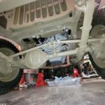
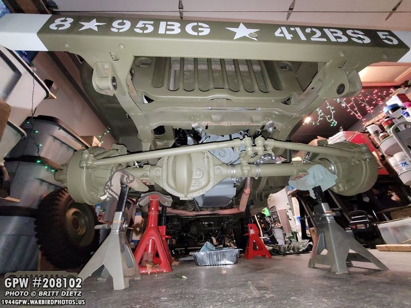
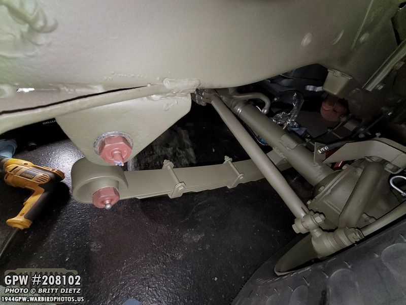
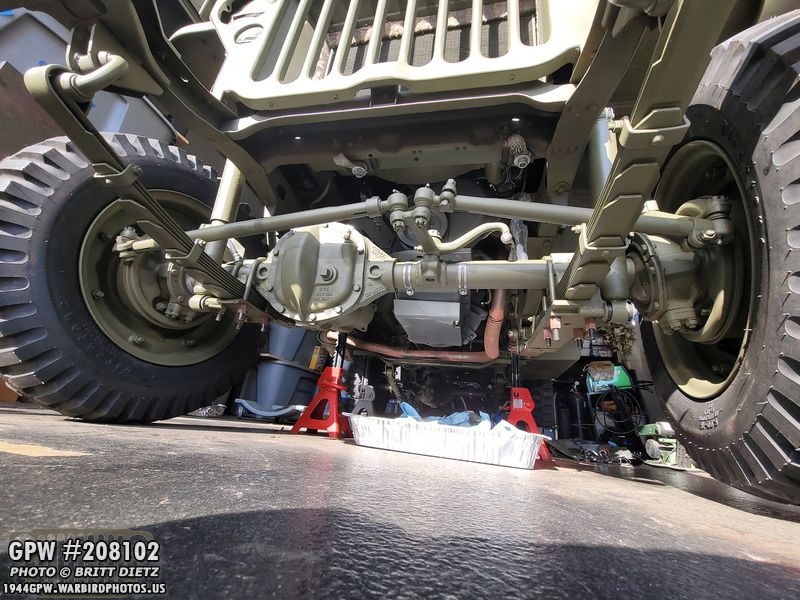
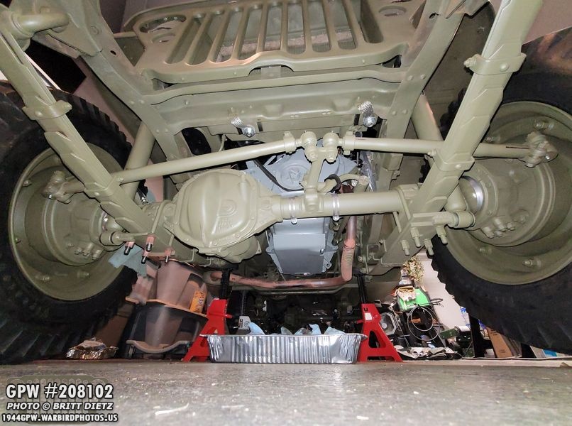
Work has progressed a lot in the last few weeks (technically, I’m actually about a week ahead of the updates… but with the limitations of Facebook and how many photos I can post in one update, which is 80, I’m a bit behind.) Here’s a look at the front axle all tucked up underneath the front of the Jeep. More on this in a bit!

Last week, I finished off with the priming of the original front GPW springs and the original Gabriel shocks.
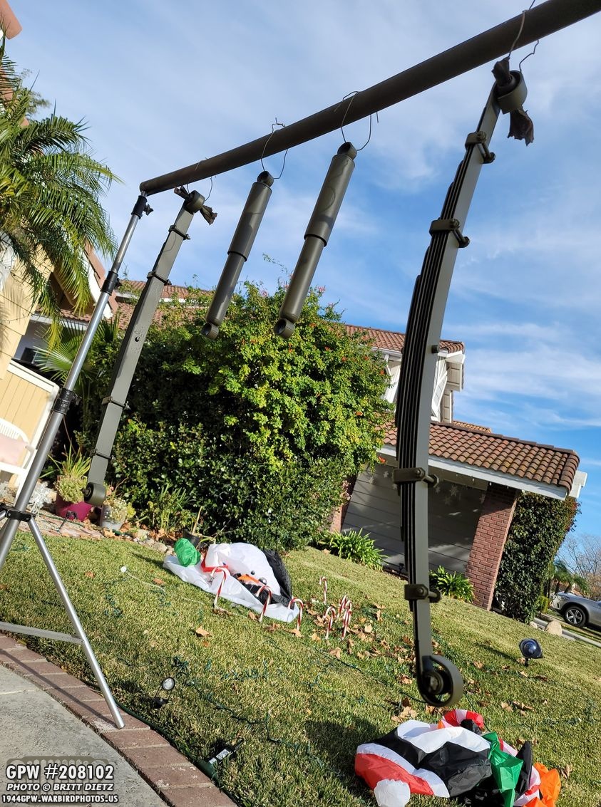
Two rather warm days meant that I could get three coats of 33070 OD Green on with the air gun! All ready for reinstall.
The custom F stamps on the spring clips look perfect.

And the markings on the shocks still show through, which is great. Remember, the shock shown on the right had almost no markings due to pitting on the shock, but both original shocks work perfectly still!

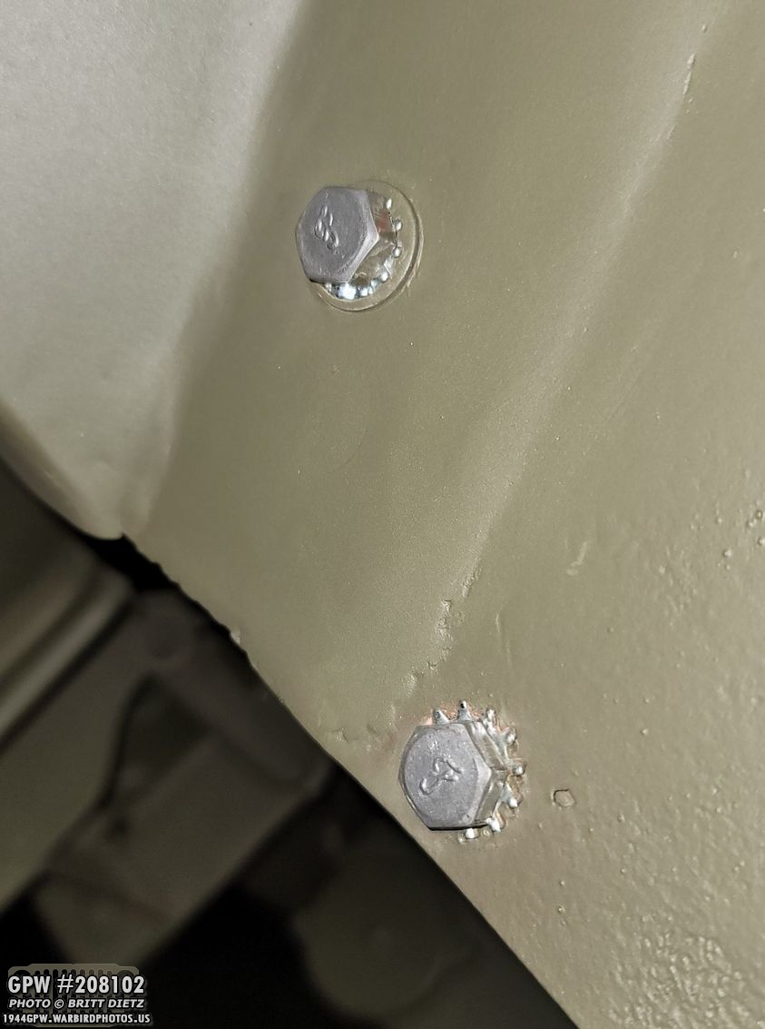
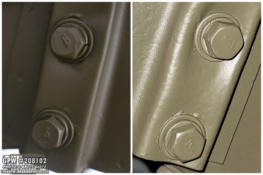
One thing that has been bugging me for a while are the bolts on my fender, which when I originally got the Jeep were just modern bolts. The original F bolts have long been lost to history. Since they were on the fender, such as these two long fender brace to frame bolts, I wasn’t in any hurry to spend a bunch of money to get custom F bolts to replace them with.

Same with these bolts on the passenger fender to cowl and step (remember, GPWs have two bolts going from the fender to the step unlike MBs which have one). Again, these are all modern bolts with the modern markings sanded away flat. Not F stamped, certainly better than modern markings on them, but I still wanted better.

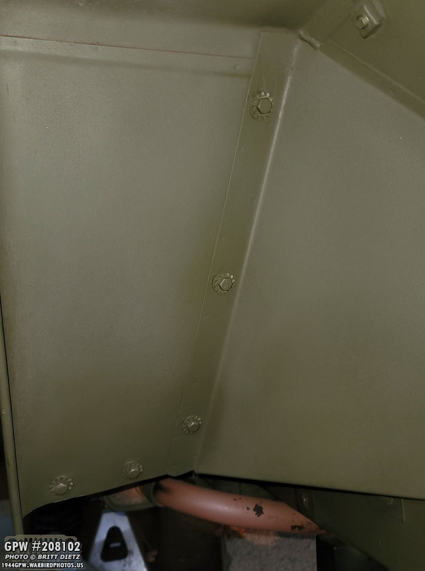
And on the driver’s side, the same thing. This photo shows all the bolts. I decided since I was waiting for the springs/shocks to dry, to do my Custom F stamp process to these since I’d gotten a lot better with them! Side Note – See the shop towel I have taped to the sharp edge of the fender? Want to take a guess why that’s there? I’ll give you a guess… involves a nice gash that’s healing on the top of my head. Be careful with those fender edges! The shop towel will, at least now, make it a bit less painful/bloody if I do it again!
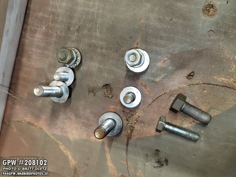
So, I didn’t want to remove the fenders completely, so I decided to take strategic bolts off a few at a time so the fender wouldn’t be totally removed, nor would it misalign the holes that I worked so hard to get the bolts into. The top on their sides are the fat skid plate to frame bolt, and the skinny exhaust pipe clip bracket to skid plate.

First step, as always, clean off the paint and any markings… then use 60 grit sandpaper to scuff up the head so the JB Weld Steel has something to grab onto.

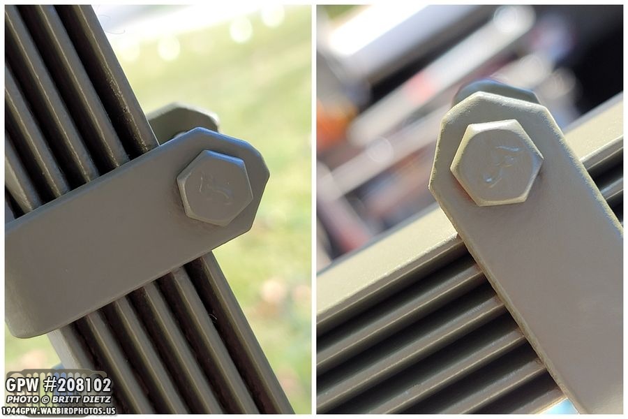
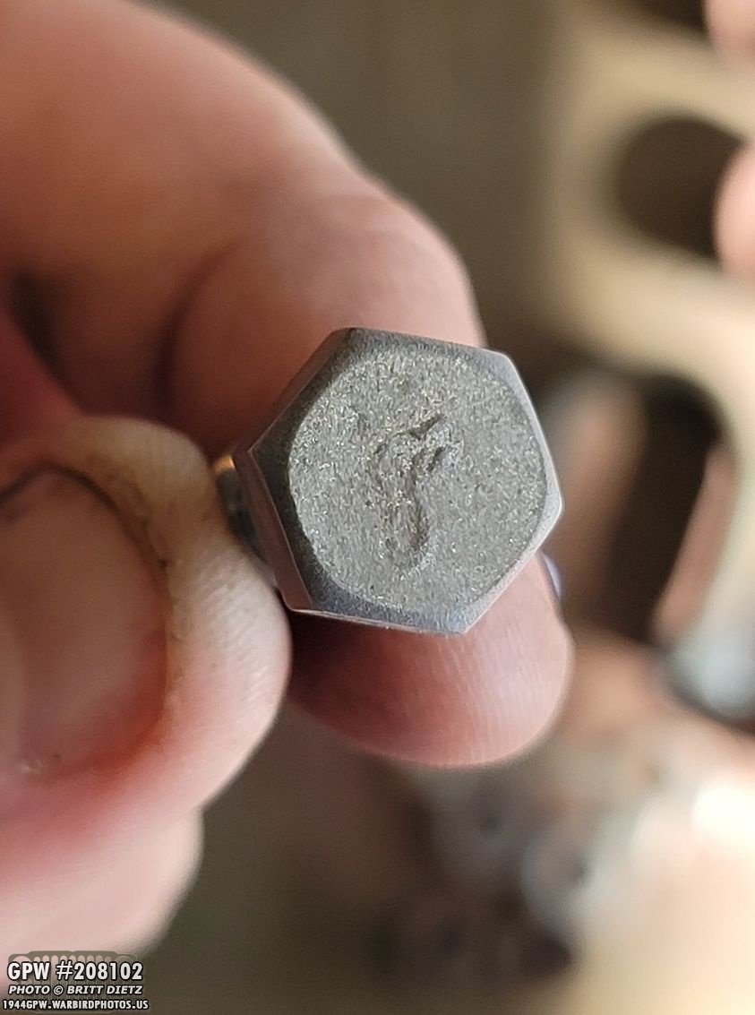
I’ve detailed the entire process of how I do these custom F stamps in a previous update, so I won’t go over it again. But on the left are the bolts after the initial stamping… and on the right after I’ve sanded down the edges and tapered the head. Looks pretty legit!
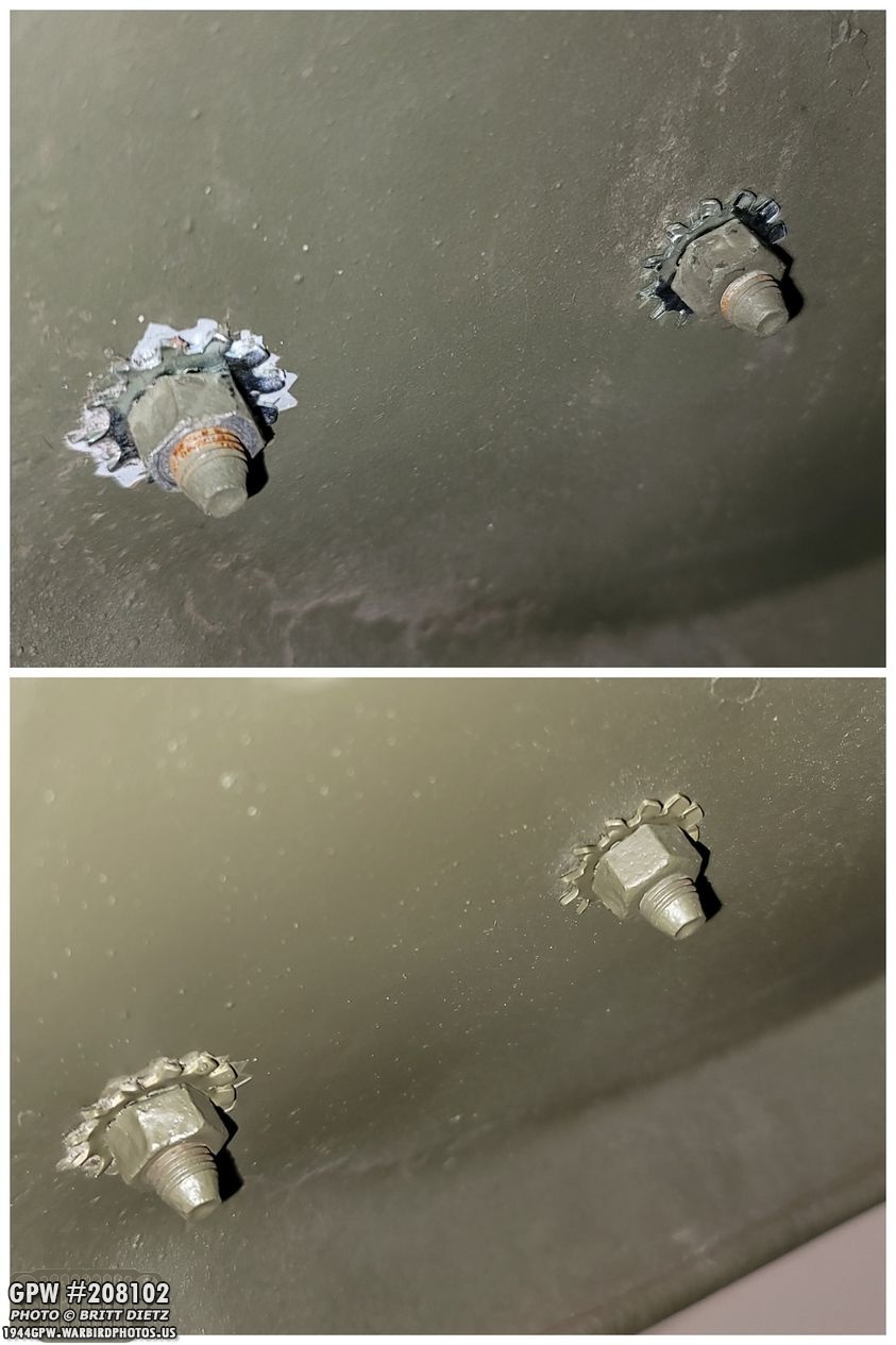
I originally had these bolts on with small 5/16 external teeth washers, but that wasn’t right… and always looked weird to me. I decided that I needed to do something different. Here are two of the bolts put back on the fender, before I made the decision to change the star washers.

And same with these, the hole on the fender is larger than the washer, and it was at this point I decided to open up the 1945 Ord9 and see exactly what was supposed to be there.

I left that first batch in as I was researching the correct hardware, and then took off the next batch of bolts and stamped them. The bottom image is the passenger side fender brace to frame bolts.
And I also took the time to put F stamps on the bolts for the master cylinder to frame. This one came out really nice.
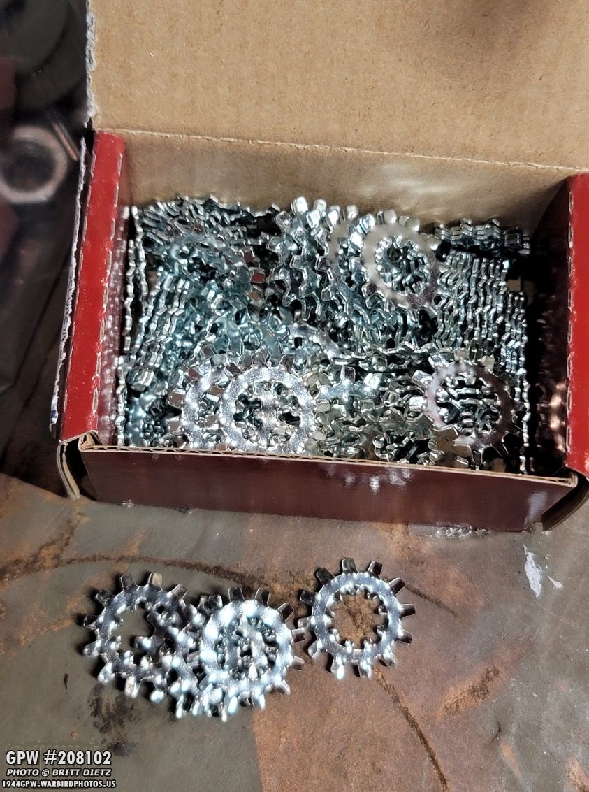
So the 1945 ORD9 says that it should be a 5/16 inner/outer star washer and a plain washer for the fender to cowl bolts, and two of these inner/outer star washers with a lock washer and plain washer for the fender to step bolts. I didn’t have any of these 5/16 inner/outer star washers, so I had to order them for pickup. I now have a box of 100 of them… which is the least amount I could order. Oh well.

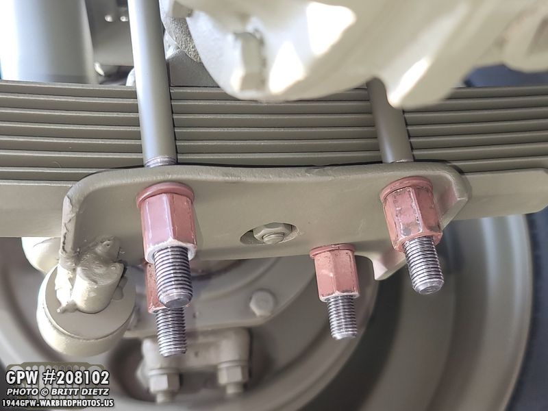
And here’s how the fender to cowl bolts should look! Nice and F stamped with the star washer and a large washer underneath that. Looks great, much better than before. Just needs paint.

Here’s a closer look at one of the bolts.
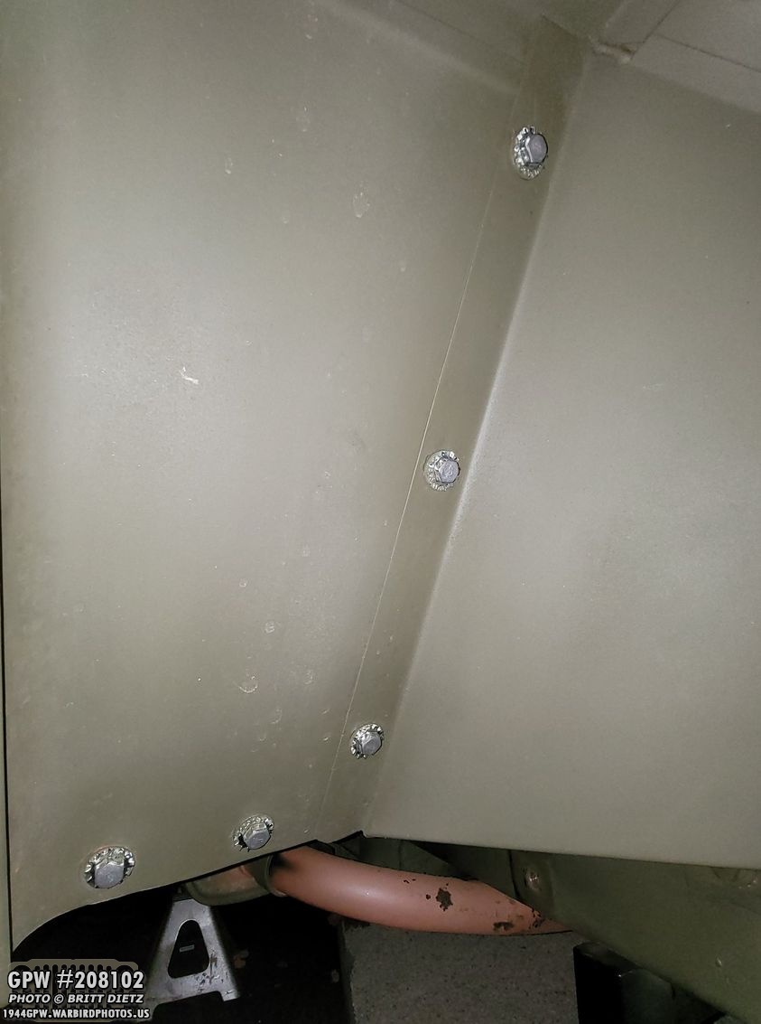
And on the bottom, you can see the two fender to step bolts, which I’ve heard technically the nut should be on this side, and the head on the other… but all this F stamping work, I didn’t want that to go to waste (and it looks so much better IMO).
Here are the two fender brace to frame bolts, all painted with the F stamps. The flash doesn’t do them justice on the right side.

And on the driver’s side, all the bolts are in place ready for paint.

And here’s how they look after primer and OD Green 33070 paint!
And the passenger side, all painted (still wet!). It’s little details, but super glad they are there now!

I also took some time to correct details on the fender blackout light bracket. The front two bolts are the original F bolts! But the back was a plain bolt, so I changed that to a repro F stamped extra I had. I also touched up the paint.
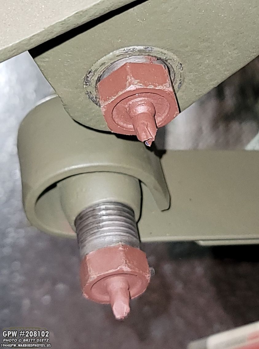
Underneath, I added the same 5/16 inner/outer washers to the front two bolts, as they should be, on the front two bolts. At the bottom is after painting. These original Ford bolts have the standard tapered ends.

Moving on, it was getting closer to time for adding the springs and the torque reaction spring! I went ahead and gathered the parts in prep.

But first, I need to get that front axle underneath the Jeep! That was quite the feat… I had the axle on a dolly, so I rolled it under the front (which is up on jacks), then I lifted one side at a time so my girlfriend could put jacks underneath the axle making them higher so I could put the tires on without them touching the ground. Lifting one side at a time wasn’t as bad as I thought, considering the axle is crazy heavy.
Looking underneath, it’s time to put some tires on!

Pretty straight forward… I put the tire onto the axle and lined up the hub studs. Once it was through, I put the lug nuts on finger tight (this driver’s side has Left-hand thread, like the rear driver’s side).
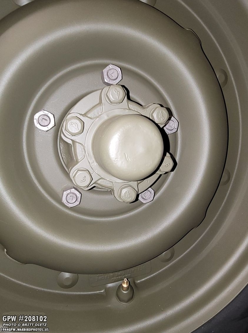
Here’s a look at the left hand lug nuts (stamped with Ls), the L stamped studs, and all the original F stamped items on the axle. The lug nuts are original WW2.

With the driver’s side finger tight, I moved on to the passenger side. Both tires on the passenger side have right-hand thread.

Here are the R stamped studs on the hub. This is all original you see in this photo.

And here’s the passenger side tire on!
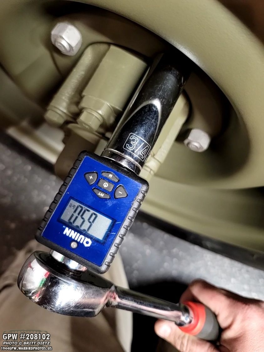
With both tires on, I went back and torqued each lug nut on both sides to 65 foot-pounds with a 3/4 socket. I did this in an X pattern for even tightening.

Even though it’s not hooked up to anything, it sure looks great seeing a proper front axle and tires!

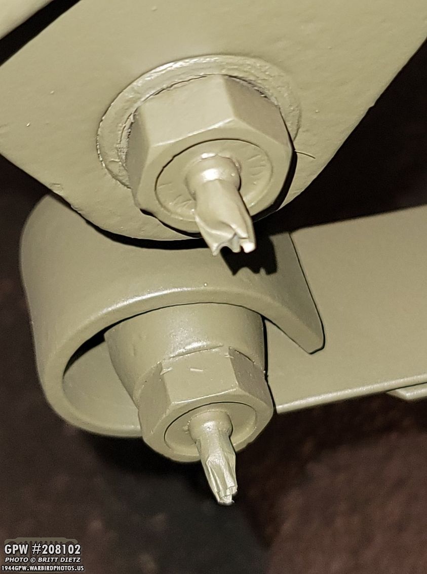
Now it’s time to get to the springs. First thing I did was test fit the torque reaction spring clamp bracket. This will be important in the next steps. Keep in mind, my Jeep lost the torque reaction spring setup when it was given CJ axles sometime in the past. Also note the custom F stamped bolt.

And on the end of the clamp, the bolt that tightens around the pivot pin head I also did a custom F stamp.

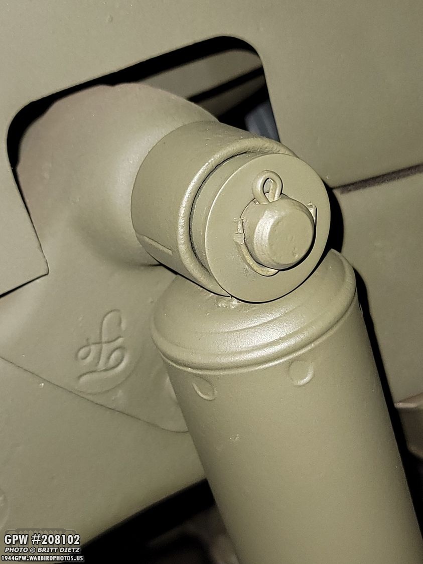
So, this is why it’s important to have that clamp bracket in place. As you drive in the pivot pin, shown here pre-greased, the hexagon head shape of the pivot pin needs to line up with the hexagon opening on the clamp. If you don’t get it lined up, you have to re-drive the pivot pin back out and start again. What I did was just loosely put the bolt in there, and as I was driving in the pinot pin, I would check to make sure it was still lined up and the clamp could fit over the head while the bolt was still in. Also, make sure you have the correct shackle for the torque reaction spring between the clamp bracket and the bracket on the frame. And of course, the pivot pin side of the spring between the frame bracket! It takes a bit of work to get that pivot pin to go through all those holes/bushings.

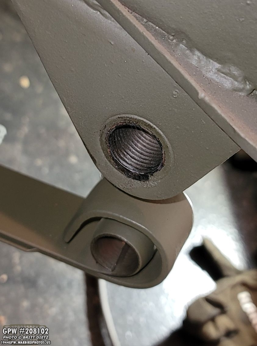
I used an 11/16 socket to hammer in the pivot pin so it is flush against the shackle (you can see the ring of paint the socket wore off on the head). As you can see, it fit perfectly in the hexagon shape on the clamp! The clamp will prevent the pivot pin from twisting at all.

After that, I added the other shackle to the backside of the pivot pin, and put on the castle nut.

Now to move on to the other side of the front driver’s side spring. This is where you center up the axle on the spring. The round bolt head of the spring goes perfectly in the recessed hole in the middle of the axle foot, as shown here.

Now it’s time to add the shackle! I got new rubber seals for the front shackles as the originals were totally shot. These were a PAIN to put on, and I had to screw them on the threads until I couldn’t turn them anymore because they were blocked by the cap bowls, and then I had to use a screw driver to push it all the way down till it was completely seated. Quite the process. I then put some grease on the threads before the next step.
I didn’t get too many photos of how I put this together (I will have better ones in a few photos when I switch to the other side), but I basically put a jack underneath the spring and kept pushing it towards the center of the spring which raised this end up to the forward shackle bracket on the frame. I was then able to put the shackle in (on the other side of what you’re seeing), and then I put the two shackle cap nuts on and screwed them in. The bottom cap nut is left thread on this side. Note – They have painter’s tape over the end of the grease fitting to protect it from painting.
With both the cap nuts tightened till they don’t move, the first front spring is now installed! It still needs the torque reaction spring, but that will come a bit later in this update.

Moving on to the other side, I documented everything a bit more. This side is easier as I don’t have to worry about any torque reaction spring things like the clamp and shackles.

Before I could put in the spring and the pivot pin, I noticed the frame bracket was caked with grease. I soaked it in some degreaser then used a steel brush and a dremel with a tiny wire wheel to clean it up. It’s not perfect, but it’s a million times better.

And as with the rear springs, the pivot pin is simple. Pre-grease it, push it in keeping the grease opening in the middle of the pin so it’s pointed straight up, push in till it stops, then use the 11/16 socket to hammer/drive the pin all the way in. The socket prevents the head from getting warped or messing up the grease fitting.

The same with the rear pivot pins, these new repros are just a bit too long for the cotter pin to line up with the castle nut grooves, so I again added a large 1/4 washer which lines up the hole to where it needs to be. Unfortunately, I don’t have any photos of the cotter pin install and touch up painting of this area (I’ll explain why in a bit).

Now that the pivot pin was in, I could work on the other side. Same as before, I used the jack (with a towel on it to protect the paint) to ‘lift’ the spring up and hole it in place until it was close enough to the bracket on the frame so the shackle can go in both holes.
Here’s a look at them aligned. I also used a drill brush to clean both holes.

Putting the shackle in the other side, I then put in the cap nuts, and screwed them on until tight. Both of these are right hand thread.

And with that, both springs are installed! The axle is just sitting on top of the springs, but it’s technically pre-installed now! At the very least, it’s aligned where it needs to be. I should also mention that before I put on the springs, I did remove the jacks that were holding up the axle, so now it’s on the wheels.
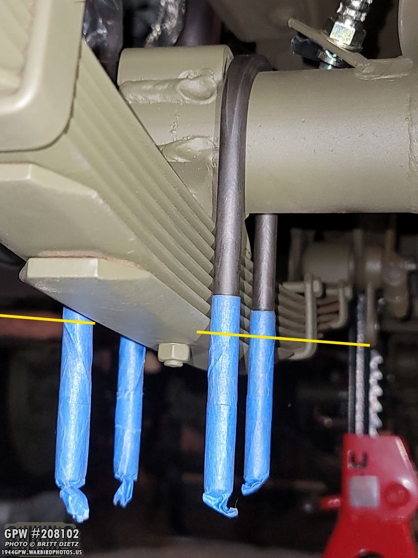
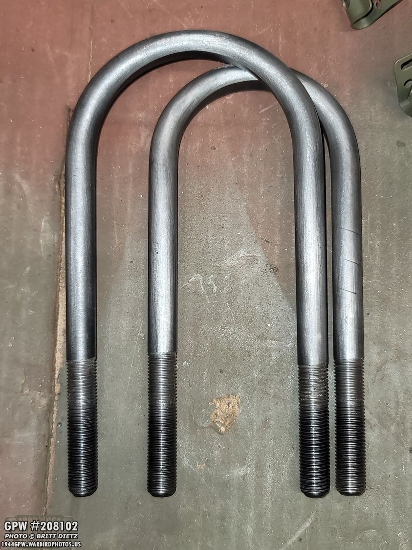
Before moving on, I wanted to check the repro U bolts for the axle. Remember, my Jeep originally had CJ axles with CJ U bolts, which are incompatible with GPW/MB axles. So I had to get a new repro set (which is F stamped) from &Ron Fitzpatrick Jeep Parts. Here I can see that the two u bolts for the torque reaction spring side are plenty long enough and the thread goes well above where the top of the leaf plate will be. Perfect! (threads are taped for painting)
But, like the rear u bolts, the passenger front side don’t have enough thread. As you can see here, the top of the plate would be about where the yellow line is… which is well above the end of the thread. As with the rears, I’ll have to add another inch or more of thread on these U bolts. The theory is that they are made for the later model GPW/MBs with the later springs that have more leaves, making them taller.

Now, I’m jumping a bit here, and I’ll explain why in a few… but first I worked on the torque reaction spring side. As you can see here, no warping at all on this! If you’ve been following along the updates recently, you know that the rear plates warped when I torqued them. It was due to the repro plates being mild steel and not thick enough. Adding the super thick two-plate torque reaction spring was well more than enough to keep everything nice and straight.

The torque reaction spring is quite heavy, and it took a lot of work trying to hold it up against the bottom of the spring, and push the U bolts through the holes, then put on the nuts. One of those many times working on Jeeps you wish you had more than two hands. But I eventually got it. These are all torqued to 60 foot-pounds (which the TRS side is torqued more than the other plates.)

So, I took a ton of photos showing how to install the torque reaction spring, how to get the torque reaction spring to ‘bend’ upwards to go into the shackle, etc. I learned my lesson long ago to back up my photos on my phone. As a photographer, that’s standard practice. So, about once a week I let my phone backup my images to my computer. This particular day, I had shot probably 80-100 photos of things in detail, and everything was great… until the next morning. My phone said the MicroSD card was unexpectedly ejected from the phone. Whaaa? After spending several hours using sophisticated recovery programs… the card was totally dead. Ugh. Total failure and unrecoverable. so I lost ALL the photos from that day. Thankfully, I had backed up the phone the day before… but still. So I didn’t want to uninstall everything and install it again, so I took photos and I’m going to try and explain it.

As you can see here, the spring is now installed with another pivot pin on the bottom of the hanging shackles. Once the torque reaction spring leaves were put on and the nuts for the U bolts tightened, I looked back here and this end of the torque reaction spring was about 5 inches below where it should be. That’s normal, I would need to somehow pull up that super thick leaf plate to get it to the bottom of the shackles.

This is what I used… a strong rachet to pull it upwards into place. How did I do this?
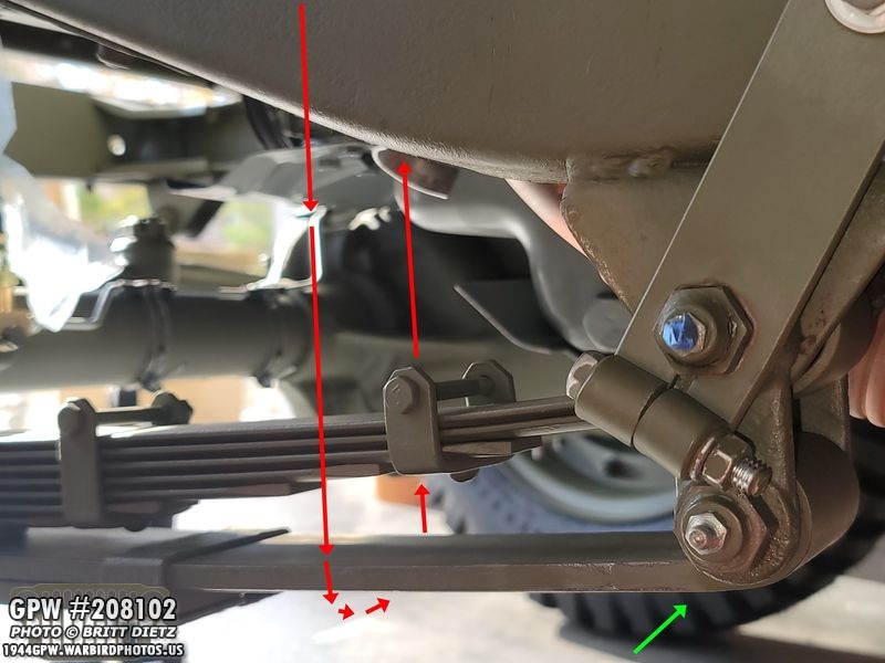
I’m sad I don’t have a photo of when I was doing it (again, I super documented it!), but basically, I had the rachet going from the top of the frame (between the fender and frame) down to the torque reaction spring like the arrows show. I then kept ratcheting it (which is really hard to do) until the plate was pulled up enough that the bushing on the leaf lined up with the bottom holes on the shackles and I could drive in the bottom pivot pin (green arrow). It took a bit of wiggling, and a rubber hammer to push over the torque reaction spring leaf over to the left a bit so it could go between the shackles. I hope I explained this well.

With everything installed, I tightened all the bolts to everything,

On the backside, I put in the cotter pins (these castle nuts didn’t need washers, thankfully, but they are special pivot pins).
The driver’s side spring and the torque reaction spring are now installed! It was a lot easier than I was expecting. I’m jumping the gun a bit here, as you can see I’ve already put on the plate, U bolts, and nuts on the passenger side… but, things didn’t nearly as well as the driver’s side did…

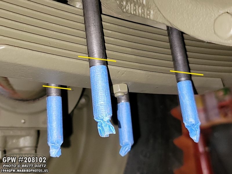
Before I could install the passenger side, I needed to add that extra thread to the U bolts. So I took out the special 7/16 hex tap, oiled up the threads, and took a deep 1 inch socket, and began adding more thread.

Here’s the result. You can see a difference in color between the threads… the red line is where the threads originally stopped, the green is what I added which is plenty.
Both U bolts now have extended thread. You might notice these U bolts are not the same, that’s correct… on the passenger side one is a normal U bolt, the other is much fatter. That is due to the U bolt actually being on part of the middle housing, which is thicker than the shaft.
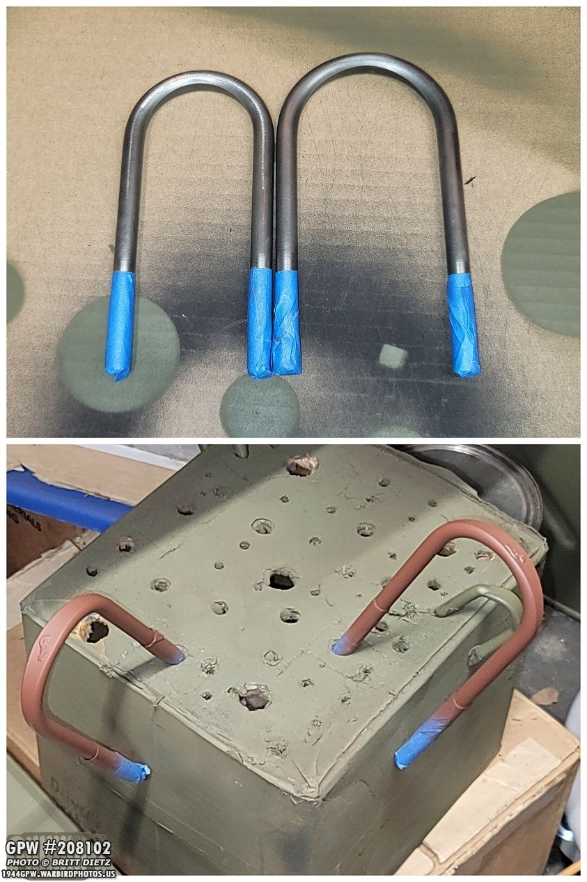
Threads taped, then they were primed and painted 33070 OD Green (not shown).

Using an original WW2 leaf plate, I put the U bolts through and put on the nuts and started tightening… remember, on the rear plates the mild steel repros bent heavily when touring them to just 35-40 foot-pounds… when the TM manual states to torque them to 50-55 foot-pounds! Well, guess what? Getting them torqued to just 45 foot-pounds HEAVILY bent the original plate. What the?!
I mean seriously warped it, even worse than the repro ones! But this is an original! It should be holding up no problem. The fact I couldn’t get them beyond 45 foot-pounds and the TM manual (for both 1942 and 1944) say 50-55 foot-pounds for these nuts…

And to make matters worse… it bent the U bolts! UGH. We’re thinking it’s because of the scalloped edges of the GPW springs… but you’d think if this was an issue during WW2, there’d be a note in the TM manuals calling for GPW springs to be torqued differently. UGH. But, have no fear, I DID find a solution to this and the rear bending which I’ll cover in-depth in next week’s update. For now, like the rear plates, I’ll leave them in since they are torqued enough for me to continue until I can replace them.

I put on the original; shocks next. They have new rubber bushings. It was tight, but I was able to carefully get the cotter pins in. Since I have to replace the passenger side leaf plate due to the bending, I won’t bend the cotter pins on the passenger side shock since I’ll need to take it off to replace the plate.

I still have to adjust the alignment of the wheels via the tie rod shafts, so they are not fully painted, but here’s a look at the tires on the front axle. Looking nice!
It’s taking shape! I can’t wait to finish this project so I can take it out for a spin with the new axles! But there’s still a lot to do.

I went ahead and bent the cotter pin on the driver’s side for the shocks since that side is totally done.

Here’s a look at the torque reaction spring all installed, set, and everything touched up with paint! Still some little bits of primer showing in between the leaf plates on this one since it shifts when on the Jeep, but I’ll fix that later. I have a bag on the flexible brake line to keep any dust and debris from getting in the line.

And a look at the clamp and pivot pins after I touched up the paint. That custom F stamp looks great now.

And the custom F stamp on the clamp looks perfect.
I also added the paint on the shackles cap nut heads.
And added paint to the driver’s side shock mounts since they are finished.

And that’s it for this week! Tune in next week for how I fixed the leaf plate bending issue, steering installation, wheel alignment, and the first time the Jeep has been on four GPW axles with combat rims in probably decades! Till next week…