 Rear Axle work – Part 2
The second part of this past week’s update, this one focuses just on the rear axle work. From diagnosing a serious issue to a full write up on adjusting the brakes! Plus, the axle turns Green at the end!

Always fun filling up at the gas station. The looks you get when you pull up in the Jeep, get out, lift up the driver’s seat, and proceed the fill up the Jeep into the tank under the seat always gets looks from the others filling up their cars!

So this update is going to be entirely about… AXLES! The ‘previous, on GPW #208102’s restoration’ recap: I have CJ (post-war) axles only my Jeep right now. They came with the Jeep when I got it. I got a pair of complete 1943 GPW axles for free almost a year ago, and I’ve been slowly taking them apart and doing a complete restoration on them.

I decided to work on the rear axle first, since I thought it would be easier and it was the one that gave me the most issues during the restoration (there was a massive spider gear explosion at some point before I got them, and it required replacements of the ring, pinion, carrier, etc and repairs). So last week, I installed the brake plates, drums, and got the spindle nuts installed. I used new nuts as the originals were rather beat up.
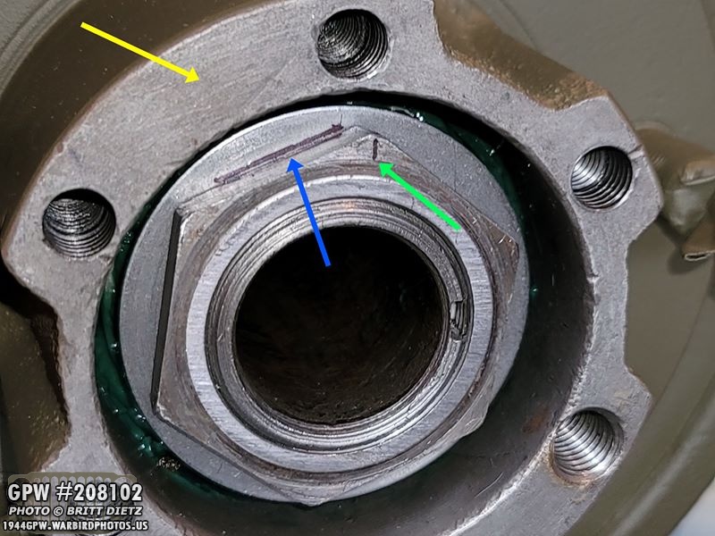
(this update is a little out of order, I’m covering this now but it was one of the last things done) All that was left to do for the spindle nuts was to peen over the large washer behind it to prevent the nut from spinning. This isn’t the easiest thing to do. First, I made sure the nut was on as tight as it needed to be. I then took a sharpie and traced the flat line (blue arrow) of the washer nearest to the top and also next to the thicker part of the hub (yellow arrow). I also marked a line (green arrow) to show where ‘up’ was. so I knew the nut was fully tightened when I put it back on.
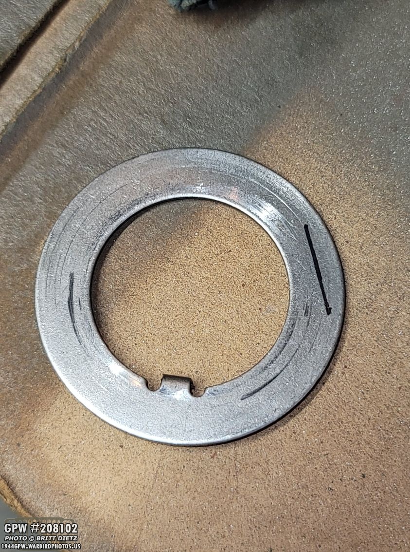
I removed the nut after that, and the washer. There’s the line I traced on that flat side of the washer. That will need to be bent forward (peened) so it locks in the outer nut. Without any special tools, my thought was to ‘prebend’ the washer using my vise (the metal is somewhat malleable), then bend it back straight to reinstall it. That way it’ll be easier to use a screwdriver to bend it back over once the nut is back on.

The result wasn’t pretty by any means, but it’s peened over and locking that nut in place. The reason you want to do this to the thicker part of the hub, as mentioned earlier, is because when you’re using the screwdriver to mangle that over, you want the thicker part to brace the screwdriver against otherwise you could break the hub on the thinner areas.

For the other side, I went a different method and took a large flat edge punch and ‘punched’ a slight line going all the way across… like pre-folding a piece of paper by slightly scoring it. This worked much better, as you can see, and it came down without a lot of effort.
This is where I’m a bit out of order, as the peening of the washer was done after the following set of images (and also note the axle is back to red). So after I had installed the spindle washer/nuts originally, I put the axle shafts in to give it all a good test. Everything seemed fine until I got to the 4th full turn of the yoke… and the whole thing stopped turning. With some force, I could break past whatever was causing it to stop, but after another 4 turns, BAM. It would stop again. UGH!

I consulted with Roger Smith and Tom Read about it, and they both had conflicting ideas/advice on what to do. Roger was concerned it was getting caught up on something and that would be very bad. Tom thought it might be catching, but might also be okay. I tried to take a look inside, as (remember) this is a NOS ring/pinion added to a take-off carrier of which all were NOT originally a part of the Jeep. Looking inside the housing, I noticed that the ring seemed to get awfully close to the back lip of the housing. Almost like it was catching ever so often. We measured how far the ring might be out of round (but it was so minimal it shouldn’t make a difference.

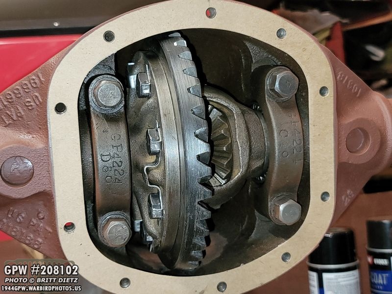
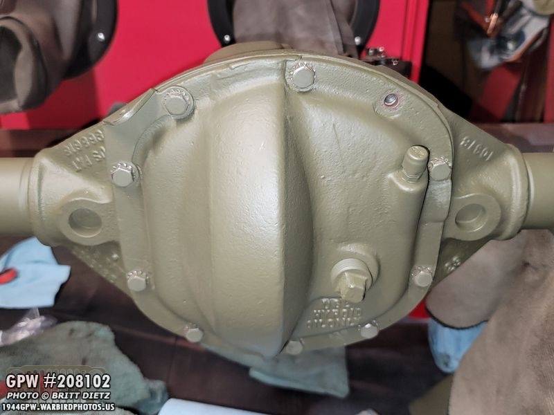
I really didn’t want to do it, after setting everything so perfect, but I went ahead and removed the carrier so I could take a look. I just felt something was wrong and it needed to be looked at. You can see the repaired damage to the bottom of the housing near the drain. That spider gear explosion was massive. So I started to look for anything that had some wear. Since it still had a nice coating of old oil, it was easy to see raw metal.
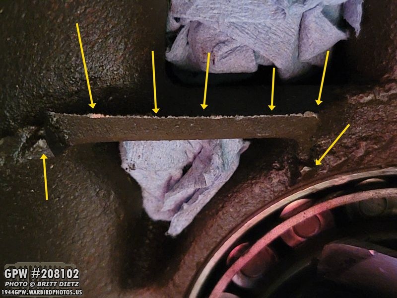
I first looked at that back lip of the housing, and sure enough, you can see there’s some wear on the upper lip edge. Also on to other spots on either side.

The pinion had some slight wear, but I was told this was normal as the ring and pinion settle with each other.

Since the only wear I could find was on that back lip, I decided to grind it down. It won’t hurt anything, and if it solves my problem, great! But, I don’t want metal dust everywhere, so I started to plug up anything that can’t have any dust get in it.
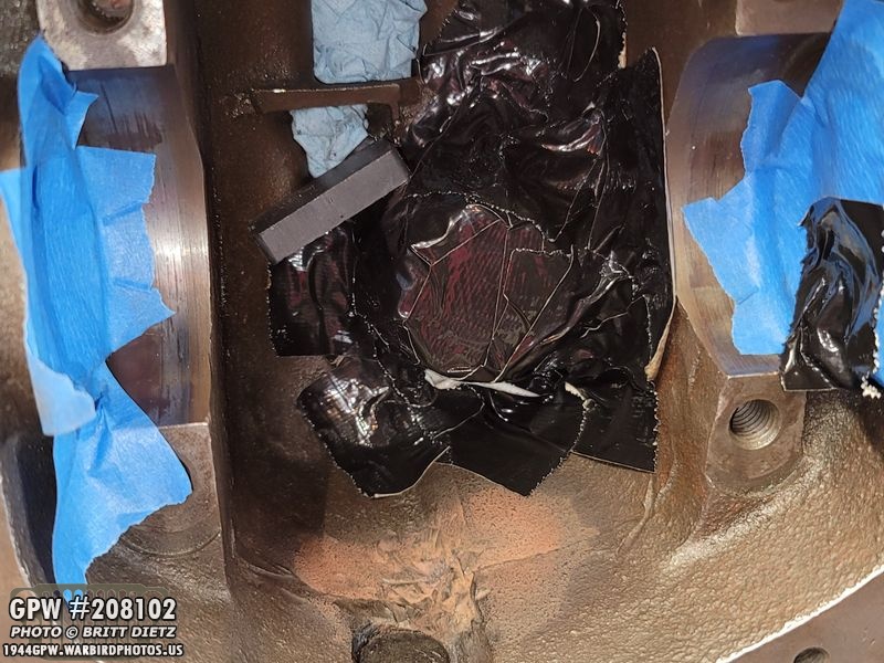
I then REALLY made sure the pinion was completely protected. I encased it with duct tape. I also added a magnet under the lip to help grab the metal shavings.

I also used a shop vac as IU was dremeling the lip. I wasn’t taking any chances with the metal debris.

I ground away that lip pretty far (before on top, after on bottom). And before I removed the tape, I did a thorough cleaning of the housing with the shov vac, compressed air, a towel, the magnet, and then did a repeat cleaning.

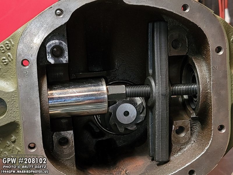
Next came the part I dreaded, putting the carrier back in as it was pain getting it in there. But, thankfully, it went in a lot easier this time and soon everything was back together.

Now the moment of truth… with the caps on, I spun the yoke… 4 revolutions, no stop! Another 4 revolutions… still not stop! YAY! As weird as it sounds, it appears that that lip was the issue. I know what you’re saying, ‘there should be way more clearance than that!’ Roger thinks it might be a combination of things… 1) the housing might not be perfectly cast, 2) the ring and carrier might be off a bit (human error), and 3) with a combination of all that working against each other it just made for this issue. But, regardless, the issue is fixed!

With everything back in the housing, it was suggested that I use some black RTV to seal the back sides of the cap screws on the back of the housing to help prevent any weeping of oil, which can happen. I liked that idea, so I went ahead and applied a coat.

It’s not pretty, but no one will really see them anyway and they’ll be painted over, so not really noticeable.

And, while I had the carrier out fixing the issue with the housing, I realized I forgot to replace the oil seals. So took them out (bottom) and grabbed my new ones from Ron Fitzpatrick Jeep Parts
Not having a oil seal installer tool, I rigged this contraption up using bearing puller parts and a large socket that was almost perfectly the side of the oil seal. It may not look even, but it perfectly pressed in the seals nice and flush! Yay innovation!

Moving on, the next big project was adjusting the brakes for proper clearance. It might seem like a daunting task, but it’s actually not that hard and pretty easy once you figure out how to do it correctly. You can use the original TM manuals online from WW2 to adjust them step by step. I used Scott Schiller’s G503 video here: https://www.youtube.com/watch?v=RKlIszhs-gE as a starting to point.

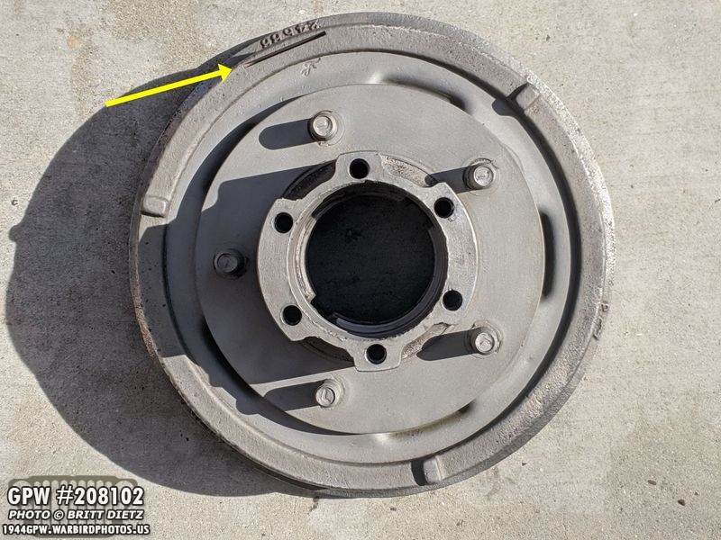
Basically, how they work… this is the outer drum of a Jeep. Inside the drum is a deep recess wall where the brakes will first make contact when you step on the petal. There are four spots where you need to adjust the clearance of the brake pads against this wall, shown here. Now, let’s look inside at the brake plate with the brake pads right underneath this drum…

Here’s an example of the brake plate inside the drum with the brake pads on either side. Those same green lines from the last photo are where the drum wall would be. You can see there’s a clearance between the drum wall and the pads. When you push the brake pedal, it sends brake fluid through the lines and into that large cylinder above the red spring. That then pushes outwards on either side pushing the brake pads into the drum walls. Adjusting the four ‘ends’ of the pads makes for proper clearance for the drum to spin without hitting the pads, and also proper timing to contact the drum to apply pressure to stop the drum from spinning when the brakes are pressed. On each drum, one pad is longer than the other. The left pad, or the pad that is facing forward on the Jeep, is longer as that needs more braking surface. The right pad, or the pad that is facing backwards on the Jeep, is shorter.

How you adjust the brakes is quite simple, you have the two anchor pins (blue arrow) which adjust how far out the bottom of the pads to the drum. This pushes the drum outwards or inwards by spinning it. The second adjustment you can’t see (yellow arrows under the brake pads, see next photo for what it looks like) is the brake eccentric, which adjusts the top of the pads. Again, you want to adjust for the tops and bottoms of the pads (green and white arrows). The pads are the purple arrows.

Here’s a look at one of the eccentric adjusters that are underneath the pads. Now, how do you adjust them? Well, it looks easy when it’s all open like this, but you can’t adjust them till you put the drum over the brake plate here, meaning you won’t see any of this again.
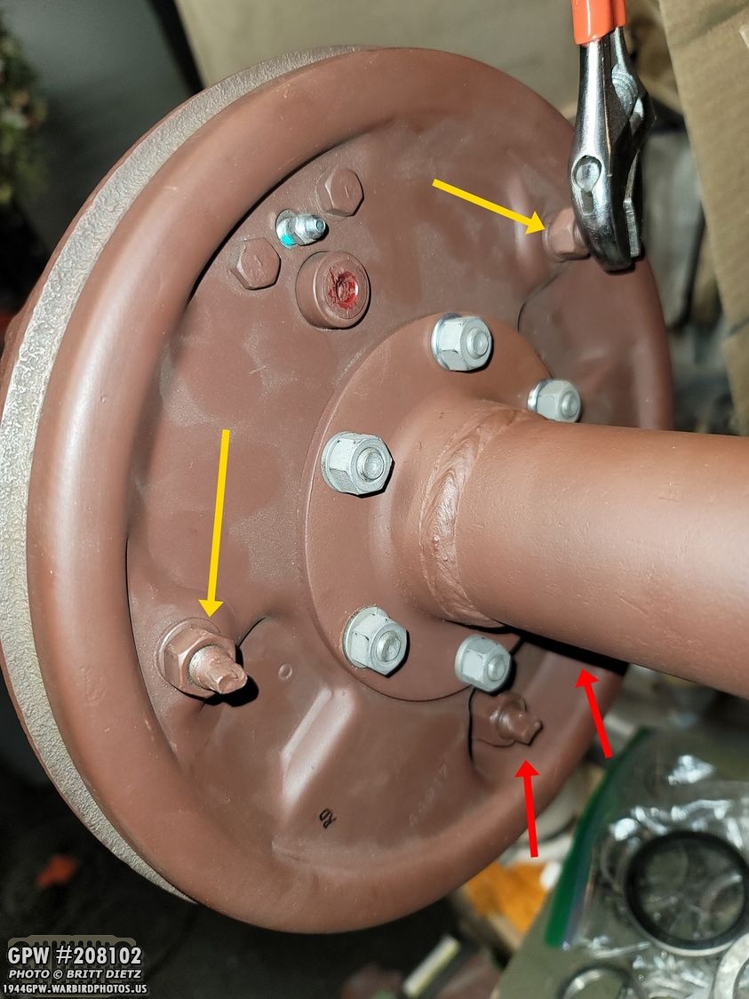
How you adjust them is on the BACK of the brake plate, with the backside of those two eccentric adjusters (yellow arrows), and the anchor pins (red arrows). You just barely losen the nuts on all four of the adjustor, and either use an adjusting wrench (shown here) or a 1/4 wrench. With the nuts just slightly loosened, you turn the screws which will push the pads outwards towards the drum, or allow them to come back in away from the drum. Now you know how the adjusting works, but how do you actually adjust them? Let’s continue…
See that slot un the drum? It’s a window to everything brakes! Make sure you slot is clear of debris so you can see through it. This slot allows you to see the drum wall and the brake pad as it gets near or makes contact with the wall. You can spin the drum around 360 and look at all four corners.

Here’s a look inside that slot with the brake pad perfectly distanced from the wall. We’re talking just a hair width’s away from it. Having a flashlight helps to see this a bunch.

There are two methods of setting brakes, and I’ve heard the pros and cons of both. The first method fully talked about in the TM manual for adjusting brakes, required a feeler gauge. This method is described in full visual detail in the G503 video: https://www.youtube.com/watch?v=RKlIszhs-gE Basically, you adjust the screws until you have slight resistance between the pads and the drum wall on the feeler gauge. You use a .008 gauge on the top and a .005 on the bottom.

Here’s a look at the .005 gauge going into the slot to check the clearance. I started with this method, and it worked great on one side of the axle. But the other side, only one of the pads worked well and the other side didn’t want to cooperate. Only the top or bottom would line up, both would not. This was probably due to the pad not being perfectly round. So, the other way is to just listen to it.

The other method, called the ‘minor adjustment’ is basically where you turn each screw, one at a time starting at the bottom anchor pins, until you hear the pad make contact with the drum (spin the drum with your hand as you adjust it). Then, turn the screw back very very slowly until that rubbing stops making a sound. Then you move on to the next screw. Make sure, once you’ve gone through all four screws, that you can spin the drum all the way around without hearing anything rubbing on the drum. I used little black sharpie marks (shown here) along the drum and the brake plate to know when that long slot window was lined up with one of the ends of each pad. So the brake plate has only one mark, but the drum has 4 marks. When the marks lined up, I could look in that slot with the flashlight and see one of the end of the pads and how close it was to the drum wall. This helped a lot.

Once you have everything adjusted, use that 1/4 wrench to hold the top eccentric adjuster screws in place (you don’t want it moving even one bit!) and use a 9/16 wrench to tighten that nut. Do this to both the top eccentrics and you’re done there!

The bottom anchor pin screws are harder to tighten. Use the same 1/4 wrench, but you’re going to need a special set of offset curved closed wrenches (see photo in comments) to spin that nut because of the recessed area that it’s in. I found the set at Harbor Freight Tools works PERFECT. Again, make sure you hold that 1/4 wrench preventing that anchor pin screw from spinning at all. Once that is tight on both, you are DONE! Spin both drums to make sure nothing moved and is making contact with the drum wall. Again, I recommend watching this video: https://www.youtube.com/watch?v=RKlIszhs-gE

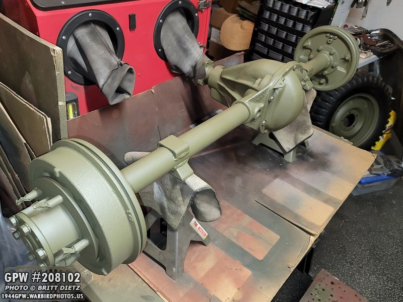
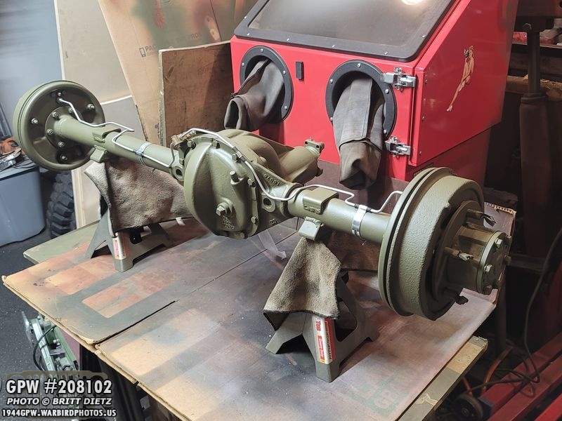
Moving on! With the brakes aligned, the spindle nuts finished with the peened washer… it was time to finally install the axle shafts for good! Make sure to put some grease on this ring on both shafts, this is where the oil seal rubs against the shaft and will help for better spinning.

With that all installed, it was time to finish priming the full axle now that it was all together!

After another full coat of red oxide primer, everything is coated!

The F stamps really stand out when painted.

And on the other side (both sides have all original items!)

The next day after a full 24 hours of drying, I used a scotch pad to roughen up the primer.

This allows the OD Green paint something to better stick to.

First coat of 33070 OD Green! I used the gallon paint from Ron Fitzpatrick Jeep Parts with some Xelene thinner.

I waited about 10 minutes between each coat (it dries so fast!) and did three full coats.

I did notice a partial F stamp I’d not noticed before on the axle outer tube next to the spring mount feet. Here’s the one on the left side.

And here’s the one on the right side, just the bottom of the F still there. The U bolts sit on this part of the axle, so it’s worn the F stamp away.
It was about this time that I did the entire grinding away at the back housing for the ring to not strike that I talked about earlier in this update. The reason I had painted it OD Green and not waited was that I was running out of hot dry days before some storms hit, so I wanted to get it painted. So after fixing that ring issue, I had to touch up the paint.

To take out the carrier, I had to remove the axle shafts. I sanded down the bolt heads again and also, because I had put three layers of OD Green over 2 layers of red oxide primer, the F stamps on the end of the shafts were a bit hard to read. So I decided to sand down them so they display better. I know, it’s a GPW owner thing.
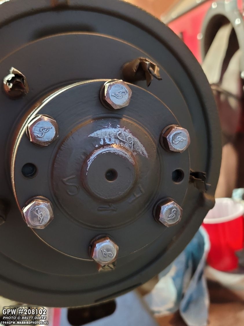
Same with the other side.

After some touch up paint, the F looks a lot easier to see! The bolts on this side were already pretty worn, so the F stamps are hard to see anyway, but they are better than before.
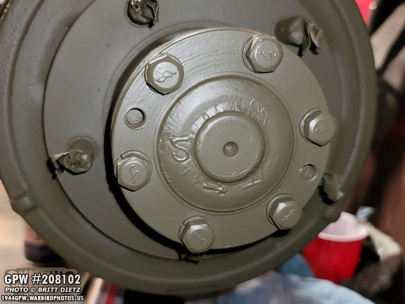
The other side is a lot better. All nice and painted!
And with that, the axle restoration is done! Now to add the brake lines

The lone clip that holds the brake line to one of the cover bolts along with the bolt, lock washer, and nut that hold the brake line tri-fitting to the bracket I painted with some Rustoleum anti-rust clear spray since I’d be leaning them unpainted.
And I’ll cover the brake line installation on Friday’s normal update! But here’s a preview from the other night when I finished! Looking nice and new!

And here we have reached the end of this two-part update for the past week! Look for the finishing of the rear axle, starting off the front axle, adding the axle bumpers to the frame, and more hood work in Friday’s update!Till then….